
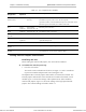
Specifications

Optimux-XLT1 Installation and Operation Manual Chapter 2 Installation and Setup
Interfaces and Connections 2-9
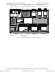
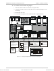
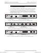
2.5 Interfaces and Connections
The T1, Ethernet, Fast Ethernet or High Speed channel connectors are located on
the unit front panel, sections A to D. Section A is dedicated to the fixed Ethernet
port. Sections (slots) B through D are allocated to T1, Ethernet, Fast Ethernet or
High Speed ports (see Figure 2-4, Figure 2-5 and Figure 2-6). Except for the fixed
Ethernet port, the front panel connections depend on the type of channel module
installed as indicated in Table 2-3.
SYNC
LOSS
AIS
OP-M
OP-M
OP-M
ETH/10BT
4T1/BAL
2T1/BAL
SYNC
LOSS
AIS
SYNC
LOSS
AIS
ETHERNET
OK
ACT
ETHERNET
OK
ACT
BA
LNK
SYSTEMPWR
FLT
TST
SYNC
LOSS
AIS
AB C D
Optimux-XLT1
RST
A
B
Section A -
Connection of Fixed Port
Sections B, C and D -
Connection of Ethernet Port and E1 Balanced
Figure 2-4. Front Panel Connections of Ethernet Port and T1 Balanced Channels
ETHERNET
OK
ACT
BA
LNK
SYSTEMPWR
FLT
TST
SYNC
LOSS
AIS
AB C D
Optimux-XLT1
RST
A
B
13
42
OP-M
DCE
V.35
4HSx2M
13
42
OP-M
DCE
V.35
4HSx2M
13
42
OP-M
DCE
V.35
4HSx2M
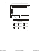
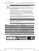
Section A -
Connection of Fixed Port
Sections B, C and D -
Connection of High Speed Ports
Figure 2-5. Front Panel Connections of Ethernet Port and High Speed Channels
SYNC
LOSS
AIS
OP-M
OP-M
OP-M
ETH-10/100BT
4T1/BAL
2T1/BAL
SYNC
LOSS
AIS
SYNC
LOSS
AIS
ETHERNET
100M
ACT LINK
ETHERNET
OK
ACT
BA
LNK
SYSTEMPWR
FLT
TST
SYNC
LOSS
AIS
AB C D
Optimux-XLT1
RST
A
B
Section A -
Connection of Fixed Port
Sections B, C and D -
Connection of Fast Ethernet and E1 Balanced Ports
Figure 2-6. Front Panel Connections of Fast Ethernet Port and T1 Balanced Channels
Order from: Cutter Networks
Ph:727-398-5252/Fax:727-397-9610
www.bestdatasource.com