
Specifications


Optimux-XLT1 Installation and Operation Manual Chapter 2 Installation and Setup
Interfaces and Connections 2-11
Table 2-4. Management, Alarm and Link Connectors
Connector Type Used to connect
POWER B Standard 3-pin plug Redundant power source (DC or AC plug), when the
redundant power supply option is selected
POWER A Standard 3-prong plug Main power source (DC or AC plug)
CONTROL/MNG 25-pin D-type female RS-232 ASCII terminal
MNG-ETH RJ-45 MNG-ETH entrance
ALARMS 9-pin D-type female Optimux-XLT1 dry contacts of two alarm relays
(major and minor) to a remote monitoring site
LINK A, TX/RX ST, SC or FC/PC Main fiber-optic link
LINK B, TX/RX ST, SC or FC/PC Redundant (backup) fiber-optic link
For the pin assignment of the connectors, refer to the Interface Specification
appendix.
Channel Connections
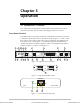
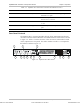
The Optimux-XLT1 has four groups of interface ports designated A to D on the
front panel of the unit.
Channel A is a fixed 10BaseT Ethernet port with an RJ-45 connector. The other
groups of interface ports should be prepared according to the ordered channel
modules (see the Channel Module Options table). Any combination of 10BaseT
Ethernet, T1 balanced, Fast Ethernet and High Speed modules can be installed in
Optimux-XLT1 slots B to D (see Figure 2-1). A vacant slot should be closed up
using a blank panel.
For T1 lines, the maximum allowable line length between the T1 ports and the
user's equipment is 655 ft (200m) according to ANSI T1.102. The cable type and
length should be selected accordingly. The length of a standard UTP cable to a
10BaseT Ethernet or 10/100BaseT station is 100 meters (330 ft).
The Interface Specification appendix provides the pin allocation for all the
connectors.
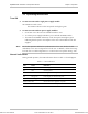
Connect the channel cables to connectors corresponding to the interface in use
(see Figure 2-4, Figure 2-5 and Figure 2-6) as indicated in Table 2-5.
Table 2-5. Cable to Interface Connections
Interface Connector Type Note
G.703 balanced RJ-45 Channel numbers 1 to 4 for the 4T1/BAL modules, 1
and 2 for the 2T1/BAL module
Ethernet, Fast Ethernet RJ-45
Physical connection
HS SCSI 26-pin To achieve the desired connector type, use the
supplied adapter cable
Order from: Cutter Networks
Ph:727-398-5252/Fax:727-397-9610
www.bestdatasource.com