
Specifications

Optimux-XLT1 Installation and Operation Manual Chapter 2 Installation and Setup
Interfaces and Connections 2-13
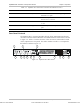
Management Connections
The Optimux-XLT1 can be managed via:
• V.24/RS-232 terminal. The connection cable to the V.24/RS-232 interface on
the unit’s rear panel should be terminated with a 25-pin D-type male connector.
The nominal length of the cable for a data rate of 19.2 kbps is 16m (50 ft).
• Ethernet port. The connection cable to the MNG-ETH interface on the unit’s
front and rear panels should be terminated with an RJ-45 connector.
Connect the management cable to the required management port. The options
available are indicated in Table 2-7.
Table 2-7. Management Port Options
Interface Connector Type Note maximum cable length
RS-232 25-pin D-type 16m (50 ft) for a 19.2 kbps data rate
Ethernet, Port A RJ-45 100m for a UTP cable, type 3
MNG-ETH RJ-45 100m for a UTP cable, type 3
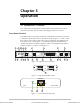
Power Connection
The Optimux-XLT1 chassis ground is connected to the protective ground (middle)
pin of the power connectors, both for the AC and DC versions of the unit.
Intentional disconnection of the protective ground is prohibited since such an
action may expose personnel to electrical shock hazards.
Before switching on or connecting any cable, the protective ground terminal
(see Figure 2-1) must be connected to the protective ground connector of the
power cord. The power plug shall only be inserted in a socket outlet provided
with a protective ground contact. The protective action must not be negated by
use of an extension cord (power cable) without a protective conductor
(grounding).
For AC or DC power connections, refer to Site Requirements & Prerequisites on
page 2-1.
Warning
Order from: Cutter Networks
Ph:727-398-5252/Fax:727-397-9610
www.bestdatasource.com