
Specifications

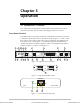

Chapter 3 Operation Optimux-XLT1 Installation and Operation Manual
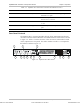
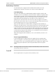
3-2 Optimux-XLT1 Controls
Table 3-1. Optimux-XLT1 Front Panel Controls and Indicators
No. Name Control State Function
OFF Indicates that the main power supply is not powered
ON (green) Indicates that the main power supply is ON and
operates normally
1 PWR A Indicator
ON (red) Indicates that a malfunction has been detected in
the main power supply or it is not powered. If the
backup power supply is installed, the Optimux-XLT1
may continue operating normally.
OFF Indicates that the backup power supply is not
installed
ON (green) Indicates that the backup power supply is ON and
operates normally
2 PWR B Indicator
ON (red) Indicates that a malfunction has been detected in
the backup power supply or it is not powered. In
this case, the Optimux XLT1 may continue operating
normally using the main power supply.
3 SYSTEM TST Indicator ON (yellow) Indicates that the system is on TEST, turn ON self
test or loop test.
4 SYSTEM FLT Indicator ON (red) Indicates a control system fault or a failure detected
during the turn ON self test.
5 SYSTEM RST Push-button Pressed Resets the Optimux-XLT1 unit using a screwdriver
ON (red) Indicates that a loss-of-signal or loss-of-frame has
been detected on the main link.
6 LINK A SYNC
LOSS
Indicator
Flashing (red) Indicates that the link is not active (the signal is
received from link B)
7 LINK A AIS Indicator ON (yellow) Indicates that an alarm indication signaling has been
detected on the link
8 LINK B SYNC
LOSS
Indicator ON (red) Indicates that a loss-of-signal has been detected on
the backup link
9 LINK B AIS Indicator ON (yellow) Indicates that an alarm indication signaling has been
detected on the backup link
10 A/B/C/D OK Indicator ON (green) Indicates link integrity on the Ethernet port
11 A/B/C/D ACT Indicator Flashing (yellow) Indicates LAN traffic on the Ethernet/Fast Ethernet
port
12 A/B/C/D
ETHERNET
Connector – Connects the Optimux-XLT1 Ethernet port to a LAN
13 B/C/D SYNC
LOSS i
Indicator ON (red) Indicates that a loss-of-signal has been detected on
channel i of the T1 interface module installed in slot
B/C/D.
Note: i is 1 to 4 for the 4T1/BAL module installed in slot B, C or D of the Optimux-XLT1 unit. i is 1 or 2 when
2T1/BAL is installed.
Order from: Cutter Networks
Ph:727-398-5252/Fax:727-397-9610
www.bestdatasource.com