
Specifications


Optimux-XLT1 Installation and Operation Manual Chapter 3 Operation
Optimux-XLT1 Controls 3-3
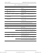
Table 3-1. Optimux-XLT1 Front Panel Controls and Indicators (Cont.)
No. Name Control State Function
14 B/C/D AIS i Indicator ON (yellow) Indicates that an alarm indication signaling has been
detected on T1 port i
15 B/C/D i Connector – Connects T1 port i of the T1 module installed in slot
B/C/D to the T1 network
16 B/C/D i Connector – Connects HS DTE to the module installed in slot B,
C or D
17 B/C/D 100M Indicator ON (green) Indicates speed of 100 Mbps on the Fast Ethernet
port
18 B/C/D LINK Indicator ON (green) Indicates link integrity on the Fast Ethernet port
Rear Panel Controls
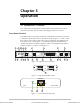
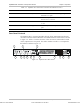
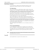
The Optimux-XLT1 rear panel provides the link, alarm, management and power
connections and the status indications associated with these connections as shown
in Figure 3-4. Table 3-2 lists the functions of the connectors and switches located
on the Optimux-XLT1 rear panel. The index numbers in Table 3-2 correspond to
the balloon numbers in Figure 3-4.
ALARMS
CONTROL/MNG
MNG-ETH
OK
LINK A (MAIN) LINK B (BACKUP)
OK
RX
TX
OK
RX TX
POWER B
CAUTION:
FOR CONTINUED
PRO TE C TION A G AINS T RI SK OF
FIRE, REPLACE ONLY WITH SAME
TY P E A N D RAT ING OF FU S E .
1.6A T 250V
100-230VAC
--
O
--
O
POWER A
1
2
3
4
5 6
7 8 11
12
13 14
10
9
VDC-IN
-480
Figure 3-4. Optimux-XLT1 Rear Panel
Order from: Cutter Networks
Ph:727-398-5252/Fax:727-397-9610
www.bestdatasource.com