
Specifications

Chapter 3 Operation Optimux-XLT1 Installation and Operation Manual
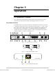
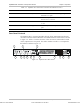
3-4 Optimux-XLT1 Controls
Table 3-2. Optimux-XLT1 Rear Panel Controls
No. Name Control State Function
1 LINK A OK Indicator ON (green) Indicates that the received signal from link A is
detected
2 LINK A (MAIN)
RX
Connector – Connects the input cable of the main link to the
main link module
3 LINK A (MAIN)
TX
Connector – Connects the output cable of the main link to the
main link module
4 LINK B OK Indicator ON (green) Indicates that the received signal from link B is
detected
5 LINK B
(BACKUP) RX
Connector – Connects the input cable of the backup link to the
backup link moduleStation Clock Module: Input
2.048 MHz signal
6 LINK B
(BACKUP) TX
Connector – Connects the output cable of the backup link to the
backup link moduleStation Clock Module: Output
2.048 MHz signal
7 ALARMS Connector – Connects the dry contacts of the major and minor
alarm relays to a remote monitoring site
8 MNG-ETH OK Indicator ON (green) Indicates link integrity on the Ethernet port
9 MNG-ETH Connector – Connects the Ethernet port to the Management port
10 CONTROL /
MNG
Connector – Connects the V.24/RS-232 management port to an
ASCII terminal
0 Turns OFF the backup power supply. The Optimux-
XLT1 is powered by the main power supply only.
11 POWER B Switch
1 Turns ON the Optimux-XLT1 backup power supply;
when set to this position, the switch lights in red.
12 POWER B Connector – Connects the Optimux-XLT1 to the AC mains or to
the backup DC power source
13 POWER A Connector – Connects the Optimux-XLT1 to the AC mains or to
the main DC power source
0 Turns OFF the main power supply. The Optimux-
XLT1 is powered by the backup power supply only.
14 POWER A Switch
1 Turns ON the Optimux-XLT1 main power supply ;
when set to this position, the switch lights in red.
Order from: Cutter Networks
Ph:727-398-5252/Fax:727-397-9610
www.bestdatasource.com