
Specifications


Optimux-XLT1 Installation and Operation Manual Chapter 3 Operation
Operating Instructions 3-5
3.2 Operating Instructions
Turn ON
➤
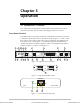
To turn ON a unit with a single power supply module:
Set POWER A switch to ON.
The PWR A indicator on the front panel must light in green.
➤
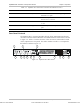
To turn ON a unit with two power supply modules:
1. Set at least one of the two rear POWER switches to ON.
2. To achieve power supply redundancy, turn ON both POWER switches.
3. The PWR A and PWR B indicator(s) on the front panel must light in green
indicating that the power consumption of the unit is shared between the two
supplies.
For the first operation and before synchronization of two units, declare the link
redundancy in the same configuration for both units. In addition, declare the timing
for both units in a valid configuration (i.e. not both units on Loop Back Timing – LBT).
Normal Indications
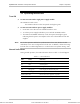
During normal operation, the LED indications shown in Table 3-3 should appear:
Table 3-3. LED Indications
LED State Indicates
PWR ON, green Power supplies of the OPTIMUX-XLT1 unit active
FLT OFF Self test passes
TST OFF No diagnostic test is performed
OK ON, green Link integrity of the Ethernet ports
ACT Flashing, yellow Ethernet port traffic
SYNC LOSS OFF No loss of receive signal on T1 ports
AIS OFF No AIS received on T1 ports
Note
Order from: Cutter Networks
Ph:727-398-5252/Fax:727-397-9610
www.bestdatasource.com