
Specifications

Optimux-XLT1 Installation and Operation Manual Chapter 4 Supervisory Port Software Configuration
The Optimux-XLT1 Interface 4-11
5. Type 1 to change a module.
6. Type 1 for module A, 2 for module B, 3 for module C, 4 for module D, or 5
for an E3 link.
7. Type 2 to change ports
8. Type 1 for port 1, 2 for port 2, 3 for port 3, or 4 for port 4.
For the E3 link, port 1 selects the main link; port 2 selects the backup link.
For an Ethernet module
:
9. Type 3
10. Set the test configuration to filter enabled or disabled. This change takes
effect only if switch SW1-3 on the ETH-TOP card or the ETH module is set to
OFF. If the switch is set to ON, the status of the interface remains filter
enabled regardless of changes made by the supervisory software.
For a Fast Ethernet module:
11. Type 1 to change a module.
12. Set the module slot to correspond to the slot of the Fast Ethernet module by
typing 1 for module slot A, 2 for module slot B, 3 for module slot C, 4 for
module slot D or 5 for E3 link.
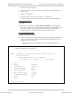
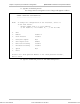
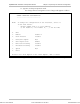
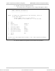
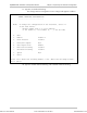
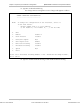
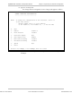
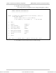
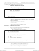
The Change Interface Configuration screen changes and appears as
follows:
LOCAL DEVICE
CHANGE INTERFACE CONFIGURATION
------------------------------
NOTE: To change the configuration of the interface, select it
in the next format:
- decimal number from 1 to 5 for modules,
(1 for module A, 2 for module B,..., 5 for E3 link)
0. Exit
1. Module module B
2. Back Pressure Disable
3. Half/Full duplex N/A
4. Auto-negotiation Enable
5. Multicast blocking Disable
6. Broadcast blocking Disable
7. Speed N/A
8. Reset
Enter your choice:
Order from: Cutter Networks
Ph:727-398-5252/Fax:727-397-9610
www.bestdatasource.com