
Specifications

Optimux-XLT1 Installation and Operation Manual Chapter 4 Supervisory Port Software Configuration
The Optimux-XLT1 Interface 4-19
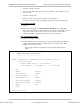
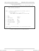
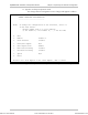
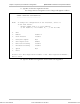
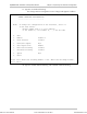
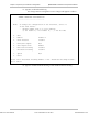
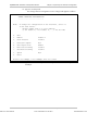
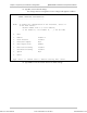
The fields needed in order to configure an interface are indicated in Table 4-5.
Table 4-5. Fields in the Change Interface Configuration Screen
Field Specifies Modules Values
Module Interface module and fiber
optic link
All 1 to 5
4T1/BAL 1 to 4
2T1/BAL FO LINK 1 and 2
ETH/10BT 1
Port Interface channel
HS 1 to 4
4T1/BAL, 2T1/BAL, Normal, Local loop,
Remote loop
FO LINK Normal, Local loop
Test Configuration Current port configuration
ETH/10BT Filter enable, Filter disable
HS Normal, Local loop,
Remote loop (in 2M
modules only)
DCD Configuration Current port configuration HS Permanent ON, Control*
CTS Configuration Current port configuration HS Permanent ON, Control**
* ON when the active link is OK (no sync loss, frame loss or AIS)
** ON when RTS is ON
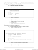
The Ethernet filtering configuration of the fixed Ethernet can be changed from this
screen. The factory setting is filter enable. The change will take affect only if
switch SW1-3 on the ETH-TOP card is set to OFF.
1. Under the remote device at the fiber-optic module no loop is available. Under
the local device at the fiber-optic module the remote loop is not available.
2. Turning the unit OFF and ON or removing and reassembling a changeable ETH
module changes back the filtering configuration to 'filter enable'.
Notes
Order from: Cutter Networks
Ph:727-398-5252/Fax:727-397-9610
www.bestdatasource.com