
Specifications

Optimux-XLT1 Installation and Operation Manual Appendix A Interface Specification
HS DTE Connector A-3
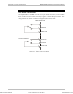
A.3 HS DTE Connector
The HS DTE module connectors are of 26-pin SCSI type. Up to four connectors
can be mounted on each module. The desired physical connector (V.35, RS-530
or X.21), is achieved using an adapter cable which is supplied with the product.
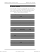
The pin assignment of the HS DTE connector is depicted in Table A-4.
Table A-4. HS DTE Connector Pin Assignment
Pin Designation Function Direction
1 GND –
26 – Unused –
2 TD- Transmit data Input
14
TD+
Transmit data Input
3 RD- Receive data Output
16
RD+
Receive data Output
4 RTS- Request to send Input
19
RTS+
Request to send Input
5 CTS- Clear to send Output
13
CTS+
Clear to send Output
6 DSR- Data set read Output
22
DSR+
Data set read Output
8 DCD- Data carrier detect Output
10
DCD+
Data carrier detect Output
17 RXC- Receive clock Output
9
RXC+
Receive clock Output
24 EXTC- External clock Input
11
EXTC+
External clock Input
15 TXC- Transmit clock Output
12
TXC+
Transmit clock Output
20 DTR- Data terminal ready Input
23
DTR+
Data terminal ready Input
18 – Unused –
21 – Unused –
25 – Unused –
7 GND –
Order from: Cutter Networks
Ph:727-398-5252/Fax:727-397-9610
www.bestdatasource.com