
Specifications

Optimux-XLT1 Installation and Operation Manual Appendix A Interface Specification
Control Connector A-5
A.5 Control Connector
Connector Pin Assignment
The optional RS-232 control port has a standard ITU-T V.24 DTE interface. The
physical interface is a 25-pin female connector, designated CONTROL/MNG. The
pin assignment of the CONTROL/MNG connector is indicated in Table A-5.
Table A-5. ITU-T V.24 CONTROL/MNG Connector Pin Assignment
Pin Designation Function V.24 Circuit Direction
1 CHAS Frame Ground 112 –
2 TD Transmit Data 103 Output
3 RD Receive Data 104 Input
4 RTS Request-to-send 105 Output
5 CTS Clear-to-send (not connected) 106 Input
6, 9–19,
21–25
– Not connected – –
7 SG Signal Ground 102 –
8 CD Carrier Detect (not connected) 109 Input
20 DTR Data Terminal Ready 108.1 Output
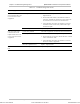
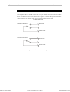
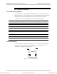
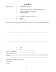
Cable Connection
If you do not wish to connect the Optimux-XLT1 to an ASCII terminal through a
modem, use a standard null-modem cable (EYN-251), or prepare a cable
according to the diagram shown in Figure A-2.
DB-25
DB-25
2
3
4
5
7
2
3
4
5
7
Figure A-2. Control Cable Wiring
Order from: Cutter Networks
Ph:727-398-5252/Fax:727-397-9610
www.bestdatasource.com