
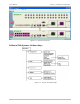
System information


User’s Manual Chapter 2 Installation and Operation
Optimux-34 Ver. 2.81 Using the Graphical User Interface (GUI) 2-9
The following ordering options are available for Optimux-34:
• USER-ETH port
• V.35 port
• One or two Uplinks
• Alarms connector.
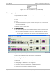
Optimux-34 Indicators
This section provides lists and color/status descriptions of the Optimux-34 device
LED indicators.
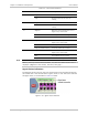
The Optimux-34 View window uses the standard RAD color codes to indicate
operational and communication status of the agent, links/ports and power
supply.
The first upper half of the system in the window contains the local LEDs and the
second lower half contains the remote LEDs. The order of the LEDs in Optimux-34
unit is as follows:
1. Sync Loss Link A
2. Sync Loss Link B
3. System Flt
4. Power A
5. Power B
6. AIS Link A
7. AIS Link B
8. 100 MNG-ETH
9. Link/Act MNG-ETH
10. 100 User-ETH
11. Link/ACT USER-ETH
12. System-TST
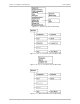
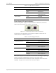
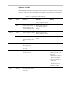
Port Status Indicators
Operational status for ports will be indicated by color within the port itself. The
port status is color-coded in gray, magenta, or blue.
Table 2-4
lists and describes
the port status colors.
There is no indication for the Control and Alarm ports.
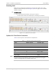
Figure 2-15. Port Status (Blue)