
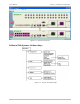
System information


User’s Manual Chapter 2 Installation and Operation
Optimux-34 Ver. 2.81 Using the Graphical User Interface (GUI) 2-11
Table 2-5. Agent Status Indicators
Location Color Description
Green Connected
White Disconnected
Local device
Red No Connection
Local Optimux only
Green Connected Remote device
White Disconnected
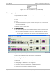
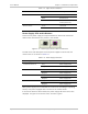
Power Supply LEDs and Indicators
There are four power supply unit representations for both local and remote
devices when both devices are present in the window.
Figure 2-17. Power Supply Status LEDs and Indicators
The LED colors and descriptions for both power supplies on both local and
remote units are as shown in
Table 2-6
.
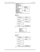
Table 2-6. Power Supply Indicators
Power Supply Color Description
Gray Power supply active Local Device Power A
Magenta Power supply fault
Gray Power supply active Local Device Power B
Magenta Power supply fault
Gray Power supply active Remote Device Power A
Magenta Power supply Fault
Gray Power supply active Remote Device Power B
Magenta Power supply fault
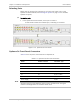
When power supply B is not available for the local unit (including its operating
switch), then power supply B does not exist on the remote device.
If the remote device is disconnected, the power supply LED colors are as last
displayed. If it goes on for the first time, the color is green.