
System information


Chapter 2 Installation and Operation User’s Manual
2-12 Using the Graphical User Interface (GUI) Optimux-34 Ver. 2.81
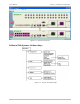
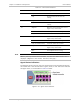
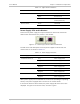
Optimux-34 LEDs
RADview/TDM for Optimux-34 displays LED indicators in real-time as they actually
appear on the device. The LED indications describe communication and operation
status of Optimux-34 and its links (see
Table 2-7, below).
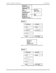
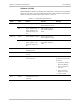
Table 2-7. Optimux-34 LED Summary
Name Color LED On LED Off Blinking
Green Power Supply A is active Power is Off on both
Power Supplies A and B
Power A
Red Power Supply A fault, or
Power Supply B is On
and Power Supply A is
Off
Power Supply is Off on
both Power Supplies A
and B
Green Power Supply B is active Power is Off on both
Power Supplies A and B
Power B
Red Power Supply B fault, or
Power Supply A is On
and Power Supply B is
Off
Power Supply is Off on
both Power Supplies A
and B
System FLT Red System Fault (Self-test
fail, Agent fault)
System TST Yellow System on test (any kind
of loop)
Sync Loss A Red Signal Loss is detected
on the main link
If the following
conditions occurs at the
same time:
• Redundancy mode is
defined as Manual
• Link A is defined as
main link
• Link A is OK (No
Signal Loss or AIS)
• Link B is active.
AIS A Yellow AIS is detected on the
main link