
- RAD Data Communications Network Router User Manual


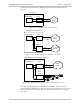

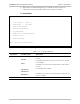

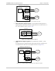
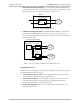
Table Of Contents
- Front Matter
- Quick Start Guide
- Contents
- Chapter 1 Introduction
- Chapter 2 Installation and Setup
- Chapter 3 Operation
- Chapter 4 Configuration
- Chapter 5 Setup Menu
- Chapter 6 Troubleshooting and Diagnostics
- Appendix A Interface Specifications and Cable Diagrams
- Appendix B Boot Manager
- Appendix C SNMP Management
- Appendix D Glossary
- DC Power Supply Connection
- Customer Response Form
Chapter 5 Setup Menu FCD-IPM Installation and Operation Manual
5-40 Interface Parameters Menu
• Main Link Local Analog Loopback – In this mode the data transmitted from
FCD-IPM to the T1 line is sent back to the receive path instead of the received
data from the T1 line. The loopback is shown in Figure 5-48.
Link1 T1 Interface
FCD-IPM
Loopback
T1
Service
Figure 5-48. Local Analog Loopback
• Sublink Local Analog Loopback (for FCD-IPM with a sublink) – In this mode
the data transmitted from FCD-IPM to the sub T1 line is sent back to the
receive path instead of the received data from the sub T1 line. The loopback is
shown in Figure 5-49.
Link1
FCD-IPM (T1 with Sub Link)
Router/Bridge
T1 Service
or PABX
Sub Link T1
Interface
T1
Service
Loopback
Figure 5-49. Local Analog Loopback for T1 and Sub T1 Links
Voice Diagnostic Tools
There are three voice diagnostic tools that are available for FCD-IPM. They can be
set independently for each voice port:
• Tone injection to the voice port – a 1 kHz signal is injected into the receive
voice port path, replacing any receive signal from T1
• Tone injection to the T1 – a 1 kHz signal is injected into the receive voice
port path, replacing any receive signal from T1, and injected into the T1
transmit path, replacing any transmit signal to T1
• Remote port loopback – the voice port signal which is received from T1 is
transmitted back to T1.