Installation and Operation Manual SPS-6, SPS-12 Multiprotocol FRAD/PAD Packet Switches
SPS-6, SPS-12 Multiprotocol FRAD/PAD Packet Switches Installation and Operation Manual Notice This manual contains information that is proprietary to RAD Data Communications Ltd. ("RAD"). No part of this publication may be reproduced in any form whatsoever without prior written approval by RAD Data Communications.
Limited Warranty RAD warrants to DISTRIBUTOR that the hardware in the SPS-6, SPS-12 to be delivered hereunder shall be free of defects in material and workmanship under normal use and service for a period of twelve (12) months following the date of shipment to DISTRIBUTOR.
Product Disposal To facilitate the reuse, recycling and other forms of recovery of waste equipment in protecting the environment, the owner of this RAD product is required to refrain from disposing of this product as unsorted municipal waste at the end of its life cycle. Upon termination of the unit’s use, customers should provide for its collection for reuse, recycling or other form of environmentally conscientious disposal.
In some cases, the users may insert their own SFP laser transceivers into the product. Users are alerted that RAD cannot be held responsible for any damage that may result if non-compliant transceivers are used. In particular, users are warned to use only agency approved products that comply with the local laser safety regulations for Class 1 laser products. Always observe standard safety precautions during installation, operation and maintenance of this product.
The maximum permissible current capability of the branch distribution circuit that supplies power to the product is 16A. The circuit breaker in the building installation should have high breaking capacity and must operate at short-circuit current exceeding 35A. Before connecting the DC supply wires, ensure that power is removed from the DC circuit. Locate the circuit breaker of the panel board that services the equipment and switch it to the OFF position.
Some SELV and non-SELV circuits use the same connectors. Use caution when connecting cables. Extra caution should be exercised during thunderstorms. When using shielded or coaxial cables, verify that there is a good ground connection at both ends. The earthing and bonding of the ground connections should comply with the local codes. The telecommunication wiring in the building may be damaged or present a fire hazard in case of contact between exposed external wires and the AC power lines.
FCC-15 User Information This equipment has been tested and found to comply with the limits of the Class A digital device, pursuant to Part 15 of the FCC rules. These limits are designed to provide reasonable protection against harmful interference when the equipment is operated in a commercial environment.
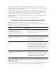
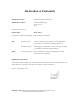
Declaration of Conformity Manufacturer's Name: RAD Data Communications Ltd. Manufacturer's Address: 24 Raoul Wallenberg St. Tel Aviv 69719 Israel Declares that the product: Product Name: SPS-6, SPS-12 Conforms to the following standard(s) or other normative document(s): EMC: Safety: EN 55022 (1994) Limits and methods of measurement of radio disturbance characteristics of information technology equipment.
Contents Chapter 1. Introduction 1.1 Overview..................................................................................................................... 1-1 1.2 Technical Specifications............................................................................................... 1-2 Chapter 2. Installation and Setup 2.1 Introduction................................................................................................................. 2-1 2.2 Unpacking ...................................
Table of Contents ii Installation and Operation Manual SPS-6, SPS-12
Chapter 1 Introduction 1.1 Overview The SPS-6, SPS-12 Multiprotocol FRAD/Switches provide easy, cost-effective access to a packet switching network. They also provide packet switching capability for both X.25 and Frame Relay. SPS-6, SPS-12 has six or twelve ports, respectively, which support aggregate data rates up to 2 Mbps (for each three ports). Each port can be configured to any of the following protocols: X.25, Frame Relay, HDLC, STM, Async, SDLC or SLIP. Switching between ports is provided for X.
Chapter 1 Introduction 1.2 Synchronous Links Installation and Operation Manual Technical Specifications Number of Links 6 for SPS-6 12 for SPS-12 Data Rate Each 3 links aggregate up to 2.15 Mbps Interface RS-232/V.24, X.21, V.35, V.36/RS-449, or RS-530 (selected during ordering) Link 1 and 2 (7 and 8) can also be: IR-ETH, ISDNS, U-INT, DDS or CSU/DSU. Connectors RS-232/V.24: 25-pin D-type, female X.21: 25-pin D-type, female, via adapter cable V.
Installation and Operation Manual Chapter 1 Introduction Power LED Indicators Link activity (for each link) Sub-channels activity Loss of synchronization (for each link) Error Overflow Test Power Physical Environment SPS-6, SPS-12 Supply Supply voltage: 115 or 230 VAC (in accordance with order), 50/60 Hz Consumption Consumption: 20W Height 4.4 cm (1.7 in) Width 43.2 cm (17.0 in) Depth 29.8 cm (11.7 in) SPS-6 Weight 1.8 kg (3.9 lb) SPS-12 Weight 2.2 kg (4.
Chapter 1 Introduction 1-4 Technical Specifications Installation and Operation Manual SPS-6, SPS-12
Chapter 2 Installation and Setup 2.1 Introduction This chapter provides mechanical and electrical installation procedures for SPS-6, SPS-12, and basic operating procedures. SPS-6, SPS-12 is delivered completely assembled. It is designed for installation as a desktop unit or mounted in a 19" rack. After installing the unit, refer to the RAD Packet Switching Guide for system configuration information and procedures.
Chapter 2 Installation and Setup Installation and Operation Manual Main Links Connections The SPS-6 has six main links connectors and the SPS-12 has twelve main links connectors. The main links connector depends on the ordered interface: • RS-232/V24: 25-pin D-type, female connector • X.21: 25-pin D-type, female connector • V.35: 25-pin D-type, female connector • RS-530: 25-pin D-type, female connector • V.
Installation and Operation Manual Chapter 2 Installation and Setup Figure 2-1. SPS-12 Internal Boards Internal Jumpers Warning Access inside the equipment is only permitted to qualified and authorized service personnel. To avoid the danger of electrical shock, always disconnect the power cable from mains before opening the unit. The SPS-6, SPS-12 main board has three internal jumpers, labeled J13, JP44 and JP39.
Chapter 2 Installation and Setup Installation and Operation Manual IR-ETH jumper, J13 When set to NOR, this jumper enables the IR-ETH interface at links 7. IR-ETH jumper, JP44 When set to NOR, this jumper enables the IRETH interface at links 1. Figure 2-2. SPS-12, Identification of Internal Jumpers Interface Board The SPS-6/SPS-12 is available with eight types of removable interface boards. The interface board types are: Warning 2-4 • V.24 (RS-232) • V.35 • V.36 (RS-530) • X.
Installation and Operation Manual Chapter 2 Installation and Setup The V.24/V.35/RS-530/X.21 interface board can be configured as DCE or DTE by changing the main jumper. The main jumper consists of multiple jumpers that must be changed together. Each board is marked DCE DTE, and the default setup is in accordance with the client’s order. The V.24 interface board is shown in Figure 2-3. Figure 2-3. SPS-M/V.24 Interface Board The interface board determines the physical layer configuration of a link.
Chapter 2 Installation and Setup 2.5 Installation and Operation Manual Installation in 19" Racks SPS-6, SPS-12 can be installed in a 19" rack. Unit height corresponds to 1U (1.75"). The width of the unit is slightly less than the available mounting width. An adapter kit provides the hardware necessary for installation of the SPS-6/SPS-12 in a 19" rack. The paragraph below provides step-by-step instructions for this procedure. Disconnect the units from AC power while performing the following procedures.
Installation and Operation Manual Chapter 2 Installation and Setup Figure 2-4. Installation of SPS-12 in 19" Rack 2.6 Cable Connections General SPS-6 has six connectors and SPS-12 has twelve connectors located on the rear panel that serve as the synchronous links. Two RJ-45 connectors are located on the front panel for the asynchronous data channels.
Chapter 2 Installation and Setup Installation and Operation Manual Synchronous Links Connection The SPS-6, SPS-12 synchronous links interfaces are configured as DTE interfaces, intended for connection to synchronous modems that are capable of providing the clock signals that determine the unit's synchronous links data rate. The synchronous link connector type depends on the interface type: • RS-232/V.24: 25-pin D-type, female connector • X.21: 25-pin D-type, female connector • V.
Chapter 3 Operation 3.1 General SPS-6, SPS-12 supports a wide range of applications, such as: • Backbone for a low-cost private synchronous network with optional connection to the public network • Expansion of the number of asynchronous channels, using RAD STM statistical multiplexers (proprietary) • Public Network access via redundant links • Running asynchronous data in X.25 packets over Frame Relay • Running asynchronous data directly over Frame Relay (e.g.
Chapter 3 Operation Installation and Operation Manual Table 3-1. Controls, Indicators and Connectors Item Control, Indicator or Connector Function 1 PWR Indicator Lights when the unit is powered. 2 Main Links Activity Indicators Indicators, one for each main link, light when the corresponding link is active (receives or transmits frames). 3 Channel Activity Indicators Indicators, one for each channel, light when the corresponding channel is active (receives or transmits data).
Installation and Operation Manual Chapter 3 Operation Rear Panel Controls and Connectors Table 3-2 lists the functions of the SPS-12 rear panel controls and connectors. The numbers under the heading “Item” refer to the identification numbers in Figure 3-2. The SPS-6 rear panel is similar to the SPS-12 but has 6 links connectors. Figure 3-2. SPS-12 Rear Panel Controls and Connectors Table 3-2.
Chapter 3 Operation Installation and Operation Manual Normal Operation During normal operation, the PWR, SYNC and MAIN indicators light continuously and the TEST, OVF and ERR indicators remain off. Channel activity indicators flash according to the traffic load, and turn off when the channel is idle. Note that when the TEST indicator lights, traffic is interrupted, even if all the other indications are normal. Power-off To turn the SPS-6/SPS-12 off, disconnect its power cable from mains. 3.
Installation and Operation Manual Chapter 3 Operation 3. In the System Control menu, select option 12. The following screen appears: THIS ACTION WILL ENABLE YOU TO DOWNLOAD A NEW SOFTWARE VERSION AFTER RESET In order to do so, please connect a terminal configured: 9600, N, 8, 1 to link no. 1 and follow the instructions on the screen. ARE YOU SURE? (YES/NO) 4. Type YES and press . 5. Reset the device by pressing the Reset button on the front panel of the module.
Chapter 3 Operation Installation and Operation Manual 3.5 What to do in Case of Malfunction Preliminary Checks In case a problem occurs, the following actions will help you return the SPS-6/SPS12 to normal operation. • Check if the SPS-6/SPS-12 is powered (PWR indicator should light). • Check if cables are properly connected. • Check if the equipment connected to the SPS-6/SPS-12 is powered and operates normally. • Check SPS-6/SPS-12 indications.
Appendix A Connector Pinouts This appendix provides information needed for the SPS-6, SPS-12 interface connections. The information presented in this appendix includes a description of the Control connector, connector pin functions and where applicable – the recommended wiring for relevant adapter cables. A.1 Interface Connectors X.21 Port Pinouts V.
Appendix A Connector Pinouts Installation and Operation Manual V.35 Port Pinouts V.
Installation and Operation Manual Appendix A Connector Pinouts RS-530 Port Pinouts A.2 Control Connector The control connector of SPS-6, SPS-12 is an RJ-45 8-pin female connector with a serial RS-232 DCE interface, intended for connection to an ASCII-based terminal. Connector pin functions are listed in Table A-1. • To connect a supervision terminal having a 9-pin connector to the control connector, use the appropriate adapter cable (CBL-RJ45/D9/F/STR or CBL-RJ45/D9/M/STR, supplied).
Appendix A Connector Pinouts Installation and Operation Manual Figure A-1.
24 Raoul Wallenberg St., Tel Aviv 69719, Israel Tel: +972-3-6458181, Fax: +972-3-6483331, +972-3-6498250 E-mail: erika_y@rad.com, Web site: www.rad.com Customer Response Form RAD Data Communications would like your help in improving its product documentation. Please complete and return this form by mail or by fax or send us an e-mail with your comments.
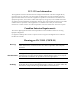
Error Report Type of Error(s) Incompatibility with product or Problem(s): Difficulty in understanding text Regulatory information (Safety, Compliance, Warnings, etc.) Difficulty in finding needed information Missing information Illogical flow of information Style (spelling, grammar, references, etc.) Appearance Other _________ Please list the exact page numbers with the error(s), detail the errors you found (information missing, unclear or inadequately explained, etc.
www.rad.com INTERNATIONAL HEADQUARTERS: 24 Raoul Wallenberg Street, Tel Aviv 69719, Israel, Tel: 972-3-6458181 Fax: 972-3-6498250, 972-3-6474436, Email: market@rad.com NORTH AMERICA HEADQUARTERS: 900 Corporate Drive, Mahwah, N.J. 07430, Tel: (201) 529-1100 Toll Free: 1-800-444-7234, Fax: (201) 529-5777, Email: market@radusa.com Publication No.