
Specifications


SPS-6, SPS-12 Site Requirements 2-1
Chapter 2
Installation and Setup
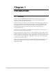
2.1 Introduction
This chapter provides mechanical and electrical installation procedures for
SPS-6, SPS-12, and basic operating procedures.
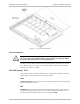
SPS-6, SPS-12 is delivered completely assembled. It is designed for installation as a
desktop unit or mounted in a 19" rack.
After installing the unit, refer to the RAD Packet Switching Guide for system
configuration information and procedures.
In case a problem is encountered, refer to the RAD Packet Switching Guide for test
and diagnostics instructions.
2.2 Unpacking
A preliminary inspection of the equipment container should be made before
unpacking. Evidence of damage should be noted and reported immediately.
To unpack the equipment:
1. Place the container on a clean flat surface, cut all straps, and open or remove
top.
2. Take out the unit carefully and place it securely on a clean surface.
3. Inspect the product for damage. Report any damage found immediately.
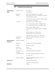
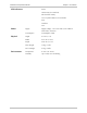
2.3 Site Requirements
Power
The SPS-6, SPS-12 unit should be installed within 1.5m (5 ft) of an easily accessible
grounded AC outlet capable of supplying 115 or 230VAC, in accordance with the
nominal supply voltage of your unit.
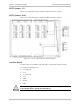
Data Channel Connections
SPS-6, SPS-12 has two RJ-45 connectors, one for each asynchronous data channel.