
Specifications

Installation and Operation Manual Chapter 2 Installation and Setup
SPS-6, SPS-12 Cable Connections 2-7
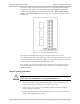
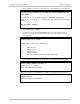
Figure 2-4. Installation of SPS-12 in 19" Rack
2.6 Cable Connections
General
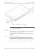
SPS-6 has six connectors and SPS-12 has twelve connectors located on the rear
panel that serve as the synchronous links.
Two RJ-45 connectors are located on the front panel for the asynchronous data
channels.
Asynchronous Data Channel Connections
The SPS-6, SPS-12 channel interfaces are configured as data communication
equipment (DCE) interfaces, thereby allowing direct connection, via RS-232 port
cables, to data terminal equipment (DTE). If modems are used to extend the range
(tail-end circuits), cross-over cables are required. Channel interfaces are
asynchronous; therefore clock signals are neither supported, nor required.