
Installation Manual

Radarfind Corporation
October 2008 V2 Collector and Remote Radio Installation Instructions Page 4
Copyright RadarFind Corp. 2008
Remote Radio wiring and Installation
RadarFind Remote Radios are connected to their Collectors with standard Ethernet Cat5e cabling. The
power and signaling used on the cables between the Collectors and the Remote Radios is not Ethernet,
although the wiring and connector pattern is the same.
Note: Never connect a Remote Radio or the Remote Radio connections on a Collector to a
standard Ethernet device or switch.
A Collector may have from 2 to 4 Remote Radios attached. Each Remote Radio location is uniquely
numbered and indicated on the facility plans provided to the installer. Each wiring run between a
Collector and a Remote Radio is identified by a unique ID which are to be clearly marked at both ends of
the cable runs to match the installation plans. (e.g. A cable run from Collector 3WE1 to Remote Radio
3WE1A) Remote Radios must be wired to the specific Collectors as indicated on the plans.
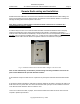
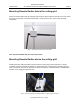
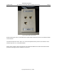
Fig 1 – Standard termination box for Remote Radio cabling at Collector location
Note: If some extraordinary circumstance prevents wiring from being installed as shown on the
plans contact RadarFind for possible alternate solutions.
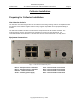
At the Collector end punch cable runs into a patch box or patch panel and mark with the Remote Radio
ID.
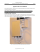
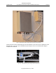
At the Remote Radio end label the cable with the Remote Radio ID and either 1-terminate the cable in an
RJ45 connector or 2-punch down to a surface mounted box with a jumper. The final cable that connects
to the Remote Radio should be white to match the case.
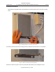
Leave 15’ of coiled extra cable, or jumper, at the Remote Radio end to allow the device to be moved if
required to optimize performance.