DE Original Betriebs- und Montageanleitung von RADEMACHER Rohrmotoren..................................................1 EN Translation of the original Operating and Assembly Manual for RADEMACHER tubular motors ............. 25 Gültig für die Serien: / Applicable for the following series: RolloTube I-line Sun Medium (ILSM) Artikelnummern / Item numbers: 2978 10 06 / 2978 20 06 / 2978 30 06 / 2978 40 06 / 2978 50 06 Bitte notieren: / Please note: Montageort: / Site of installation: ..................
i DE Sehr geehrte Kunden... ...mit dem Kauf dieses Rohrmotors haben Sie sich für ein Qualitätsprodukt aus dem Hause RADEMACHER entschieden. Wir danken Ihnen für Ihr Vertrauen. Die RADEMACHER Rohrmotoren sind unter Aspekten des größten Komforts entstanden. Mit einem kompromisslosen Qualitätsanspruch und nach langen Versuchsreihen sind wir stolz, Ihnen dieses innovative Produkt zu präsentieren. Dahinter stehen alle hochqualifizierten Mitarbeiterinnen und Mitarbeiter aus dem Hause RADEMACHER.
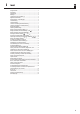
i Inhalt DE Sehr geehrte Kunden.........................................................................................2 Diese Anleitung................................................................................................2 Zeichenerklärung..............................................................................................2 Abbildungen.....................................................................................................4 Legende der Gesamtansicht (Abbildung ) ........
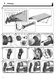
i DE Abbildungen 1 (1) (2) (3) (4) (5) (6) (7) (8) (9) (10) (2) (4) (5) (11) (6) (12) (7) (8) (9) (10) (19) (13) 2 5 7 (8) (2) 3 (14) (3) (4) (3) (7) (18) 4 (10) (15) (16) 4 (10) 6 (4) 8 (1) (11) (8) (17) (3) (2) (6) (8) (11)
i Legende der Gesamtansicht (Abbildung ) (1) Seitenabdeckung (2) Montageschrauben (3) Lagerbock (4) Click-Antriebslager (5) Federring (6) Antriebskopf (7) Setztaste (8) Adapter (9) Rohrmotor (10) Mitnehmer (11) Markisenwelle (12) Markisentuch (13) Motorkabel (inkl.
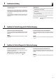
DE Allgemeine Sicherheitshinweise Bei allen Arbeiten an elektrischen Anlagen besteht Lebensgefahr durch Stromschlag. Bei unsachgemäßem Gebrauch besteht erhöhte Verletzungsgefahr. ◆ Der Netzanschluss des Rohrmotors und alle Arbeiten an elektrischen Anlagen dürfen nur durch eine zugelassene Elektrofachkraft nach den Anschlussplänen in dieser Anleitung erfolgen, s. Seite 13/14/15. ◆ Verbieten Sie Kindern mit ortsfesten Steuerungen zu spielen.
i DE Funktionsbeschreibung Die RADEMACHER Rohrmotoren RolloTube I-line Sun dienen zum elektrischen Betrieb (Ein-/Ausfahren) von Markisen. Die Rohrmotoren sind mit dem neuen Safe-Drive-Verfahren zur Positionserfassung, Drehmomentüberwachung und Hinderniserkennung ausgestattet. Die kompakte Bauweise und eine vollautomatische Endpunkteinstellung des Antriebs sorgen für eine einfache, komfortable Montage.
DE Wichtige Montagehinweise Durch die falsche Montage der Markise besteht eine hohe Verletzungsgefahr. Durch direkten Wettereinfluss auf den ungeschützten Rohrmotor besteht Kurzschluss- und Brandgefahr. Lassen Sie alle Montage- und Reparaturarbeiten an der Markisenanlage nur durch einen Fachbetrieb ausführen. Der montierte Rohrmotor darf niemals direktem Regen oder Schneefall ausgesetzt sein, das kann zu lebensgefährlichen Situationen durch Kurzschlüsse und zu seiner Zerstörung führen. Prüfen Sie, ...
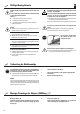
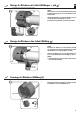
Montage des Mitnehmers mit Freilauf (Abbildungen 3 und .a )* DE * = Im Auslieferungszustand ist der Mitnehmer schon ab Werk vormontiert. 3.a (10) WICHTIG Soll der Rohrmotor mit der automatischen Endpunkteinstellung und mit der Hinderniserkennung arbeiten, müssen Sie den Mitnehmer (10) mit Freilauf montieren. (16) Schieben Sie den Mitnehmer (10) so auf den Abtriebsadapter (16), dass er Freilauf hat und hinter dem Rastbügel (15) einrastet. 1.
DE Den Rohrmotor in die Markisenwelle schieben (Abbildung 4) Schlagen Sie nie den Motor (9) mit Gewalt in die Markisenwelle (11) ein. STOP 1. WICHTIG Die Setztaste (7) des Rohrmotors muss später leicht zugänglich sein und das Motorkabel (13) muss ohne Knick verlegt werden. Das führt zu seiner Zerstörung. Schieben Sie zuerst den Mitnehmer (10) in die Markisenwelle (11). 2.
Vorbereitungen bei Verwendung von Präzisionsrohren (Abbildungen 4. 4.d .a - .e ) DE Markieren Sie vier Befestigungslöcher und bohren Sie diese anschließend durch das Präzisionsrohr in den Mitnehmer (10). ACHTUNG u Bohren Sie nie tiefer als 10 mm in den Mitnehmer (10). u Nie im Bereich des Antriebs bohren. Das führt zu seiner Zerstörung. STOP 4.e 5. Das Präzisionsrohr am Mitnehmer (10) festschrauben oder vernieten.
Montieren des Antriebslagers (Abbildung 5 - 7) Antriebslager (als Clicklager) 1. 2. Schieben Sie anschließend den Lagerbock (3) wieder auf die Quertraverse (18) der Markise bis das Antriebslager (4) vollständig am Antriebskopf (6) einrastet (s. Abbildung 7). 3. Prüfen Sie, ob die Setztaste (7) des Motors (9) frei zugänglich ist. Korrigieren Sie gegebenenfalls die Position des Antriebslagers (4) am Lagerbock (3). Schrauben Sie das Antriebslager (4) am zuvor ausgebauten Lagerbock (3) fest (s.
DE Sicherheitshinweise zum elektrischen Anschluss Bei allen Arbeiten an elektrischen Anlagen besteht Lebensgefahr durch Stromschlag. ◆ Der Netzanschluss des Rohrmotors und alle Arbeiten an elektrischen Anlagen dürfen nur durch eine zugelassene Elektrofachkraft nach den Anschlussplänen in dieser Anleitung erfolgen. ◆ Trennen Sie die Zuleitung allpolig vom Netz und sichern Sie sie gegen unbe absichtigtes Einschalten. ◆ Prüfen Sie die Anlage auf Spannungsfreiheit.
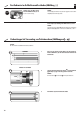
DE Das Motorkabel (Abbildung k) 1. 11 (7) Verbinden Sie das Motorkabel (13) per Stecker mit dem beiliegenden Anschlusskabel und führen Sie den Anschluss gemäß der folgenden Adernbelegung durch.
Parallelschaltung von mehreren Motoren (Abbildung m) Installationsbeispiel DE Die Parallelschaltung mehrerer RADEMACHER Rohrmotoren ist möglich. Die Anzahl der parallel zu schaltenden Motoren ist von der Belastbarkeit der Schaltstelle und der Sicherung abhängig. 13 HINWEIS Im Falle der Parallelschaltung ist jedoch keine individuelle Steuerung des einzelnen Motors mehr möglich.
DE Verwendung der Setzleitung zur manuellen Endpunkteinstellung Verwendung der Setzleitung (j) bei Erstinstallation Über die Setzleitung (j) wird die Funktion der Motorsetztaste (7) nach außen geführt. Wenn Sie die Setzleitung (j) an einen externen Taster anschließen (s. oben), können Sie diesen externen Taster als Setztaste zur Einstellung der Endpunkte nutzen.
DE Endpunkte einstellen Sie haben verschiedene Möglichkeiten zur Einstellung der Endpunkte, die wir Ihnen im Folgenden beschreiben: WICHTIG ◆ Sie müssen für beide Laufrichtungen, Auf (▲)/Ab (▼), Endpunkte setzen, bei deren Erreichen der Motor abschaltet. u Den oberen Endpunkt automatisch (mit Hilfe der Blockiererkennung) einstellen und den unteren Endpunkt manuell setzen. ◆ Der Rohrmotor muss vollständig eingebaut sein. ◆ Die Setztaste (7) am Rohrmotor muss frei zugänglich sein.
Den oberen Endpunkt automatisch einstellen und den unteren manuell setzen 1. Die Markise vollständig einfahren und gegen den oberen Anschlag fahren, bis der Rohrmotor automatisch stoppt. ▲ ▼ 2. 3. 4. 5. DE WICHTIG Greifen Sie während der Fahrt nicht in den Ablauf ein. Die Markise muss ohne Unterbrechung einfahren. Anschließend fährt der Rohrmotor die Markise automatisch in die Gegenrichtung.
DE Oberen / unteren Endpunkt manuell einstellen 1. 2. ▲ ▼ SET oder Schalter/Steuerung zuerst in den Hochlauf (▲) / Tieflauf (▼) schalten. HINWEIS Trennen Sie bei falscher Drehrichtung die Zuleitung vom Netz und vertauschen Sie die beiden Adern L1 und L1 . Die Setztaste* drücken und festhalten, bis der gewünschte Endpunkt erreicht ist. * am Motor, am Schnurschaltersetzgerät (20) oder am externen Taster. Die Markise fährt ein / aus. 3. 4.
DE Den Rohrmotor konfigurieren Mit Hilfe eines Schnurschaltersetzgerätes (20) können Sie bei der Erstinstallation den Rohrmotor individuell konfigurieren. Folgende Einstellungen sind möglich. HINWEIS Weitere Einstellungen können Sie mit dem optional erhältlichen RT ConfigTool durchführen. Bitte beachten Sie dazu die Angaben auf unserer Internetseite (www.rademacher.de). u Die Werkseinstellungen laden.
i DE Was tun, wenn... ? Mögliche Ursache: ...die Setzleitung vor Ort nicht verfügbar und die SET-Taste des Rohrmotors nicht zugänglich ist, die Endpunkte aber manuell eingestellt werden sollen. ◆ Die Netzspannung fehlt. Lösung ◆ Der Thermoschutz hat angesprochen. u Zur Durchführung dieser Einstellung müssen die beiden Steuerleitungen für Auf (s) und Ab (t) jeweils separat an die Phase (L) angeschlossen werden. ...
i DE Was tun, wenn... ? ...die Setzleitung vor Ort nicht verfügbar und die SET-Taste des Rohrmotors nicht zugänglich ist, die Werkseinstellungen aber geladen werden sollen. Lösung u Zur Durchführung dieser Einstellung müssen die beiden Steuerleitungen für Auf (s) und Ab (t) jeweils separat an die Phase (L) angeschlossen werden. u Verwenden Sie dazu entweder einen externen Taster mit zwei Schaltkontakten oder das im Fachhandel erhältliche Schnurschaltersetzgerät (20).
i DE Technische Daten Motorserie ILSM xx Nenndrehmoment: Leerlaufdrehzahl: Nennspannung: Frequenz: Nennleistung: Stromaufnahme: Einschaltdauer (KB): Anzahl der Adern: Aderquerschnitt: steckbares Anschlusskabel (Gummi): Endschalterbereich: (Anzahl d. Umdreh.) Isolationsklasse: Schutzklasse: Schutzart n. VDE 700: Motorlänge ohne Lager: Rohrdurchmesser: Schalldruckpegel (LpA): Anzahl parallel schaltbarer Rohrmotoren (Bei Verwendung der RADEMACHER Steuerung, z.B. Troll Comfort) i Nm U/min V Hz W A Min.
i Garantiebedingungen RADEMACHER Geräte-Elektronik GmbH gibt 5 Jahre Garantie für Neugeräte, die entsprechend der Einbauanleitung montiert wurden. Von der Garantie abgedeckt sind alle Konstruktionsfehler, Materialfehler und Fabrikationsfehler. Ihre gesetzlichen Gewährleistungsansprüche bleiben von dieser Garantie unberührt.
DE Original Betriebs- und Montageanleitung von RADEMACHER Rohrmotoren..................................................1 EN Translation of the original Operating and Assembly Manual for RADEMACHER tubular motors .............. 25 Applicable for the following series: RolloTube I-line Sun Medium (ILSM) Item number: 2978 10 06 / 2978 20 06 / 2978 30 06 / 2978 40 06 / 2978 50 06 Please note: Site of installation: ............................................................................................
i EN Dear Customer, With your purchase of this tubular motor, you have decided in favour of a quality product manufactured by RADEMACHER. We would like to thank you for your confidence. RADEMACHER tubular motors have been developed with the greatest possible convenience in mind. Having applied uncompromising quality standards, and carried out thorough testing, we are proud to be able to present you with this innovative product. It is brought to you by all the highly-qualified personnel here at RADEMACHER.
i Contents EN Dear Customer,...............................................................................................26 These instructions...........................................................................................26 Key to symbols...............................................................................................26 Figures..........................................................................................................28 Key to the overall view (Figure 1) ........
i EN Figures 1 (1) (2) (3) (4) (5) (6) (7) (8) (9) (10) (2) (4) (5) (11) (6) (12) (7) (8) (9) (10) (19) (13) 2 5 7 (8) (2) 3 (14) (3) (4) (3) (7) (18) 28 (10) (15) (16) 4 (10) 6 (4) 8 (1) (11) (8) (17) (3) (2) (6) (8) (11)
i EN Key to the overall view (Figure 1) (1) Side cover (2) Assembly screws (3) Bearing block (4) Click drive bearing (5) Retaining spring (6) Drive head (7) Set button (8) Adapter (9) Tubular motor (10) Catch (11) Awning shaft (12) Awning fabric (13) Motor cable (incl.
EN General safety instructions Danger due to electric shock when working on all electrical systems. Incorrect use leads to an increased risk of injury. ◆◆ The electrical connection for the tubular motor and all work on the electrical systems may only be undertaken by an authorised qualified electrician and in accordance with the connection diagrams in these instructions, see pages 37/38/39. ◆◆ Train all personnel to safely use the tubular motor.
i EN Functional description The RADEMACHER RolloTube I-line Sun series of tubular motors are designed for the electrical operation of awnings (extending / retracting). The tubular motors are equipped with the new Safe-Drive system for position detection, torque monitoring and obstacle detection. The drive‘s compact design and fully automatic end point configuration ensures for straightforward and convenient installation.
EN Important assembly instructions Incorrect assembly of the awning may lead to an increased risk of injury. There is a risk of short-circuits and fire in the event of direct weather influences to the unprotected tubular motor. For this reason, arrange to have all installation and repair work carried out by a specialist firm. The mounted tubular motor may never be subjected to direct rain or snow, as this may lead to life-threatening situations due to short-circuits and damage to the motor. Check:...
Mounting the catch with freewheel mechanism (Figures 3 and .a )* EN * = The catch is supplied pre-installed by the factory. 3.a (10) IMPORTANT If the tubular motor is to be operated with automatic end point configuration and obstacle detection, then the catch (10) must be mounted with free-wheeling action. (16) 1. Slide the adapter (10) onto the drive adapter (16) so that it can freewheel and so that it engages behind the retaining clip (15).
Slide the tubular motor into the awning shaft (Fig. 4) Never knock the motor (9) with force into the awning shaft (11). STOP 1. IMPORTANT The set button (7) for the tubular motor must be easily accessible and the motor cable (13) must be laid without kinking. Doing so will cause serious damage. First slide the catch (10) into the awning shaft (11). EN 2. Subsequently press the tubular motor into the awning shaft (11) so that the adapter (8) is fully inserted into the awning shaft (11).
Preparation for use of precision tubes (Figures 4. 4.d .a - .e ) EN Mark the four fastening holes and subsequently drill them through the precision tube in the catch (10). ATTENTION ◆◆ Never drill deeper than 10 mm into the catch (10). ◆◆ Never drill in the area of the drive. Doing so will cause serious damage. STOP 4.e 5. Screw or rivet the precision tube to the catch (10). Use four self-tapping sheet metal screws, plastic screws or pop rivets.
EN Mounting the roller shutter casing (Fig. 5 - 7) Drive bearing (as click bearing) 1. 2. Subsequently slide the bearing block (3) back onto the cross member (18) of the awning until the drive bearing (4) fully engages on the drive head (6) (see Fig. 7). 3. Check that the set button (7) on the motor (9) is easily accessible. Correct the position of the drive bearing (4) on the bearing block (3) if necessary. Screw the drive bearing (4) to the previously removed bearing block (3) (see Fig. 5).
EN Safety instructions for electrical connection Danger due to electric shock when working on all electrical systems. Fixed-installation devices... ◆◆ The electrical connection for the tubular motor and all work on the electrical systems may only be undertaken by an authorised qualified electrician and in accordance with the connection diagrams in these instructions. ...must be equipped on the installation side with a circuit-breaker for each phase in accordance with DIN VDE 0700.
EN The motor cable (Figure k) 1. 11 Connect the motor cable (13) to the connecting cable supplied by means of a connector and make the connection according to the following wiring configuration.
Parallel connection of several motors (Fig. m) Installation example EN It is possible to connect numerous RADEMACHER tubular motors in parallel. The number of motors to be connected in parallel is dependent on the capacity of the switchgear and circuit-breakers. 13 NOTE It is not possible to control individual motors if the equipment is connected in parallel.
EN Use of the set line for manual end point adjustment The set lead (j) enables the function of the motor set button (7) to be externally positioned. If the set lead (j) is connected to an external button (see above), you will be able to use this button as a set button for configuring the end points.
EN End point adjustment You have various options for configuring the end points, which are described in the following section: IMPORTANT ◆◆ End points must be set in order to switch off the motor when they are reached for both directions of travel up (s)/ down (t). ◆◆ Setting the upper end point automatically (by means of blockage detection) and manually setting the lower end point. ◆◆ The tubular motor must be fully installed. ◆◆ The set button (7) must be easily accessible.
Automatically setting the upper end point and manually setting the lower end point EN 1. The awning will first retract to the upper stop until the tubular motor switches off automatically. ▲ ▼ IMPORTANT Never interrupt the sequence while the process is running. The awning must retract without interruption. 2. 3. 4. 5. Subsequently the drive shifts the awning in the opposite direction. SET or SET or SET or Press and hold the corresponding set button* until the lower end point is reached.
EN Manually setting the upper / lower endpoints 1. 2. ▲ ▼ SET or First set the switch / controller to upward travel (s) / downwards travel (t). NOTE In the event of incorrect direction of rotation, disconnect the lead from the mains and exchange wires L1 and L1 . Press and hold the corresponding set button* until the desired end point is reached. * on the motor, the cord switch device (20) or the external switch. The awning retracts / extends. 3. 4.
EN Configuring tubular motors The tubular motors can be individually configured with the help of a cord circuit setting unit (20). The following configurations are possible. NOTE Additional settings can be undertaken with the optionally available RT ConfigTool. Please refer to the information on our Website www.rademacher.de. ◆◆ Reload the factory settings.
i EN What to do if... ? Possible cause: ...The set line is not available locally and the SET button on the tubular motor is not accessible, however, the end points should be manually configured. ◆◆ Mains power not available. Solution ◆◆ The thermal protection system has triggered. ◆◆ In order to carry out this configuration, it is necessary to separately connect the two control lines for up (s) and down (t) to phase (L). ...
i EN What to do if... ? ...The set line is not available locally and the SET button on the tubular motor is not accessible, however, the factory settings are to be loaded. Solution ◆◆ In order to carry out this configuration, it is necessary to separately connect the two control lines for up (s) and down (t) to phase (L). ◆◆ Either use an external button with two switching contacts or the commercially available cord circuit set device (20).
i EN Technical specifications ILSM xx Motor series Nominal torque: Idling speed: Nominal voltage: Frequency: Nominal power: Power consumption: Cyclic duration factor (KB): Number of wires: Core cross section: Plug-in connecting cable (PVC): End switching range: (number of revolutions) Insulation class: Protection class: Protection class in accordance with VDE 700: Motor length without bearing: Tube diameter: Noise pressure level (LpA): Number of parallel tubular motors connectible (when using RADEMACHER
i EN Warranty conditions RADEMACHER Geräte-Elektronik GmbH provides a 5 year guarantee for new equipment installed in accordance with the installation instructions. All construction faults, material defects and manufacturing defects are covered by the warranty. For the warranty to be applicable, the new device must have been purchased through one of our approved specialist retailers. Proof of this can be provided by presenting a copy of the bill.