02 m5 500 series Opto Compressor Module owner’s manual Rev A all contents © Grace Design/ Lunatec LLC 2434 30th Street, Boulder, CO 80301 USA tel 303.443.7454 fax 303.444.4634 info@gracedesign.com / www.gracedesign.
Welcome and thanks for purchasing the Grace Design m502 optical compressor. We build all of our products to be completely reliable and easy to use, so you can concentrate on making great recordings. While you will find the m502 is completely straightforward to use, we do ask that you spend a little time reading this manual to help avoid any common user difficulties. In the event that you do encounter any technical difficulties with this or any of our products, feel free to call us at 303-443-7454.
Important Safety Information GENERAL Indoor use only Ordinary Protection: This equipment should not be exposed to dripping or splashing. Avoid placing objects filled with liquids, such as vases or glasses, on this equipment. Mains supply voltage fluctuations are not to exceed ±10% of the nominal supply voltage. Pollution Degree 2 Maximum Relative Humidity: <80% Operation temperature range: 10 °C to 40 °C Storage and transportation temperature range –40 °C to 70 °C Maximum altitude: 3000m (9843 ft.
Features • Elegantly simple, purist feedback design optical compressor for signal leveling with a minimum of sonic artifacts • Subtle dynamic control to heavy compression, the sonic character of the source remains intact • Comprehensive control set includes input level, threshold, attack, release, ratio and makeup gain • Bright, easy to read 10 segment LED gain reduction meters • Bi-color output peak LED lights green with signal present and red 6dB before clipping • Pin 7 & 9 connections to Radia
Installing and Connecting Before you do anything, please register your unit with us as soon as possible. We provide a 5 year transferable warranty on all of our products and registering it with us makes is easy if and when help becomes necessary. So please take a few minutes to complete the enclosed warranty registration card and mail it in, or simply fill out the warranty registration form on our web site. Thank you! Installing the m502 in a 500 series rack 1. Open your m502 box.
• Pin 9 is connected to the tip of the 1/4” TRS connector labeled “OMNIPORT” on the Radial Workhorse or “OPT IN” on the Purple Sweet Ten Rack for stereo linking or side chain signal input. • Pin 11 is connected to send an unbalanced audio output to the Radial Workhorse “BUSS FEED”. If you are using either of these racks, please refer to their documentation for operating with these connections.
not attenuate the initial impulse of the signal, select a longer attack time. Using a slower attack time may be more appropriate with signals with a slower, more gradual envelope (strings, woodwinds). SETTING THE RELEASE RATE The rate at which you want the circuit to release its attenuation of the signal (release phase) is set with the release control. This is the functional opposite of the attack control. If the signal has a shorter decay, it may be best to set a shorter release time.
SIDE CHAIN CONTROL For connecting a side chain signal to the m502, you need a 500 series rack which has a provision for an auxiliary input to the module via pin 7 (Radial Engineering Workhorse or the Purple Audio Sweet Ten win again in our book). Connect an unbalanced side chain signal via the tip of a 1/4” TRS cable to the aux in. This signal will be available for side chain input via pin 7.
PEAK LED The PEAK LED is used to monitor any peaks within the m502. It turns green at -15dBu and red at +20dBu. The m502’s internal headroom is +26dBu, so occasional red is fine, just a warning that you are 6dB away from clipping. If the light is mostly red, then you are probably clipping the unit and all your gear downstream.
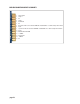
CARD EDGE CONNECTOR CONTACT ASSIGNMENTS 1. 2. 3. 4. 5. 6. 7. 8. 9. 10. 11. 12. 13. 14. 15.
Specifications (Preliminary) GAIN RANGE Input Trim Output Trim -10, 0, +10dB -10 - +10dB Compression Threshold Range Attack Range -15 - +15 dBu 3 – 200 ms Release Range 0.03 – 3 s Ratio Range 1:1 – 12:1 Gain Reduction 0 – 20dB THD+N 1kHz, 22Hz-22kHz BW @ 0dB Gain +10dBu out <0.002% INTERMODULATION DISTORTION @ 0dB Gain +20dBu out SMPTE/DIN 4:1 7kHz/50Hz <0.007% OUTPUT NOISE 22Hz-22kHz BW @0dB Gain <-84dB CMRR @0dB Gain, 3.
Warranty Grace Design warrants all of our products to be free of defective parts and workmanship for a period of five years. This warranty period begins at the original date of purchase and is transferable to any person who may subsequently purchase the product during this time. This warranty excludes the following conditions: normal wear and tear, misuse, customer negligence, accidental damage, unauthorized repair or modification, cosmetic damage and damage incurred during shipment.
Manual Revisions Revision Page A all Change Date Initials 1/30/2012 edg page 13