Radicom Research, Inc.
Table of Contents Introduction ...................................................................................................... 3 Features ............................................................................................................ 4 Applications ..................................................................................................... 4 Specifications ...................................................................................................
Introduction Thank you for purchasing Radicom’s RB540 series Class 1 Bluetooth multimedia module. We are committed to providing you quality service and technical support. The RB540 series module is designed to meet requirements for long-range wireless audio functionality. The RB540 series offers a quick and simple solution for adding wireless audio Bluetooth communications to OEM’s products.
Features • • • • • • • • • • • • • • • • • • Bluetooth 3.
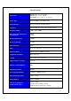
Specifications Dimensions RB540-a: 0.7” x 1.55” x 0.10” RB540-c: 0.7” x 1.33” x 0.10” RB540HM(-a/-c): 1.02” x 1.83” x 0.39” Device Type Embedded Bluetooth OEM module Audio Interface Microphone Input / Speaker Outputs Frequency ISM 2.4 GHz short-range radio frequency band Frequency Range 2.400 – 2.483.
RB540 Module Block Diagram 6
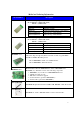
Model and Ordering Information Model Number RB540-a Description Surface mount, long range Class 1 Bluetooth Audio module with PCB antenna. Model: RB540-a (8M FLASH-default) RB546-a (16M FLASH) Firmware Options RB540-c Description BPU21.004 Standard Rx (Default) BTW11.003 TrueWireless (Master & Slave)- contact Radicom BPT52.004/BPR52.004 Tx/RX (two-way)- contact Radicom BPT54.002/BPR54.
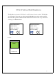
FCC & IC Label and Model Identification The RB540 module family is FCC Part 15 and IC (Industry Canada) certified. The RB540 is also CE marked. The modules are labeled with the RB540 module model number and FCC Part 15 ID, IC registration number and CE mark. The label can be found on top of the metal shielding on the RB540 Module. Radicom Research Inc. Radicom Research Inc.
Federal Communication Commission Interference Statement This equipment has been tested and found to comply with the limits for a Class B digital device, pursuant to Part 15 of the FCC Rules. These limits are designed to provide reasonable protection against harmful interference in a residential installation. This equipment generates, uses and can radiate radio frequency energy and, if not installed and used in accordance with the instructions, may cause harmful interference to radio communications.
This device is intended only for OEM integrators under the following conditions: The transmitter module may not be co-located with any other transmitter or antenna, As long as 1 condition above is met, further transmitter test will not be required.
Industry Canada statement: This device complies with Industry Canada’s licence-exempt RSSs. Operation is subject to the following two conditions: (1) This device may not cause interference; and (2) This device must accept any interference, including interference that may cause undesired operation of the device. Cet appareil est conforme aux CNR exemptes de licence d'Industrie Canada.
This device is intended only for OEM integrators under the following conditions: 1) The transmitter module may not be co-located with any other transmitter or antenna. As long as 1 condition above are met, further transmitter test will not be required. However, the OEM integrator is still responsible for testing their end-product for any additional compliance requirements required with this module installed.
Le produit final doit être étiqueté dans un endroit visible avec l'inscription suivante: "Contient des IC: 2377A-RB540". Manual Information to the End User The OEM integrator has to be aware not to provide information to the end user regarding how to install or remove this RF module in the user’s manual of the end product which integrates this module. The end user manual shall include all required regulatory information/warning as show in this manual.
CE Declaration of Conformity For the following equipment: Radicom Research Inc. Wi-Fi Module Mode(s): RB540-a, RB540-c are herewith confirmed to comply with the requirements set out in the Council (European parliament) Directive on the Approximation of the Laws of the Member States relating to Electromagnetic Compatibility of Radio and Telecom device (1999/5/CE). For the evaluation regarding this Directive, the following standards were applied: EN 300328 V1.8.1: 2012 EN 62311:2008(MPE) EN 301489-1 V1.9.
Layout Design Suggestions • General Layout Rules- All Printed Circuit Boards must comply with UL94V0 standard for flammability. Always use RoHS compliant Parts and materials. • Suggestions for Layout: 1. Do not place Power circuit, X’tal, Inductor, etc. near RF area. 2. The bigger Antenna clearance area, the better. The Antenna itself needs to stay away from any circuit or component at least 2mm. Antenna clearance area means Top and Bottom both required to be cleared. 3.
RB540 Series SMD Module Mechanical Diagram & Pin Assignments Module Dimension: RB540-a: 0.70” x 1.55” x 0.10” RB540-c: 0.70” x 1.33” x 0.10” * Height = 0.10” (2.
Recommend RB540-c SMD Module PCB Layout Dimension 17
Recommend RB540-a SMD Module PCB Layout Dimension 18
RB540 Series SMD Module Interface Signal Definitions Pin# Pin Name Description I/O Voltage range 1 GND - Ground --- 2 RF I/O RF input/output --- 3 GND - Ground --- 4 GND - Ground --- 5 3V3 I 3.3V input VDD: 3.1V – 3.6V 6 GND - Ground --- 7 PIO(3) I/O Programmable I/O line 8 PIO(2) I/O Programmable I/O line 9 AIO(1) I/O Programmable I/O line Vih: 0.625 VDD – VDD + 0.3V Vil: -0.3V – 0.25 VDD Voh: 0.75 VDD – VDD Vol: 0 – 0.125V Vih: 0.625 VDD – VDD + 0.3V Vil: -0.
Pin# Pin Name Description I/O Voltage range 23 SPI_MISO O Synchronous serial interface data output A19 I Dual mode selection (8Mb default pull low) 25 VOLPIO(14) I/O Programmable I/O line 26 BAT_CHECK PIO(11) I/O Programmable I/O line 27 MUTE PIO(5) I/O Programmable I/O line 28 I2C_SCL PIO(6) I/O Programmable I/O line 29 PCM_IN I Synchronous PCM data input 30 PCM_SYNC I/O Synchronous PCM data strobe 31 PCM_OUT O Synchronous PCM data output 32 PCM_CLK I/O Synchronous
Pin# Pin Name 45 LED1 O LED1 46 LED0 O LED0 47 MIC_BIAS O Microphone Bias 48 MIC_R_P I Microphone Right Positive Voh: 0.75 VDD – VDD Vol: 0 – 0.125V Voh: 0.75 VDD – VDD Vol: 0 – 0.125V For best regulation limit current between 0.32mA and 1.53mA Range: 0V ~ 1.5V 49 MIC_R_N I Microphone Right Negative Range: 0V ~ 1.5V 50 MIC_L_N I Microphone Left Negative Range: 0V ~ 1.
RB540HM(-a/-c) Mechanical Drawing Note: Suggested mating female connectors: 1. 2. Through Hole: Samtec P/N. #SQT-114-01-L-S (RoHS) SMT: Samtec P/N.
RB540HM (-a/-c) Interface Signal Definitions Pin Name Type 1 NC - 2 KEY No Pin 3 PIO2 I 4 PIO3 I 5 LINEIN_DET I 6 VOL+ I High to increase volume 7 MUTE I Low to mute system 8 CALL_END I High to End Call 9 BAT_CHECK I Battery Check 10 VOL- I High to decrease volume 11 SPI_MOSI I SPI Signal, MOSI 12 SPI_CLK I SPI Signal, CLK 13 SPI_CS I SPI Signal, CS 14 SPI_MISO O SPI Signal, MISO 15 PIO8 O Active Low, LED 4 16 PIO4 O Active Low, LED 3 17 18 19 3V
RB540MB Development Board Figure& Functional Descriptions JP1 SPK1 LED1 LED2 SP-R LED3 LED4 SP-L MIC1A USB1 PSW1 BATT1 The RB540MB Development PCB has white silkscreen legend or reference designations located by the switches and connectors described below. Switches Functional Description PSW1 Power Toggle Switch: This switch controls the power to the RB540HM module that is mounted on the RB540MB board. To remove the RB540HM, turn off PSW1.
Operating the RB540MB for Standard RX The RB540-a/c has optional firmware for Standard HFP+A2DP Stereo RX. This firmware allows the user to establish a Bluetooth stereo connection between a RB540-a/c module and a Bluetooth capable cell phone. After a Bluetooth connection is established with the phone, the user can pick up a phone call or play music from his phone. The following will explain how to use the RB540MB switches to control the RB540-a/c module with the standard HFP+A2DP RX firmware.
Operating the RB540MB for TrueWireless Stereo Sound The RB540 has optional firmware for True Wireless Stereo sound. This firmware allows the user to establish a Bluetooth stereo connection between two RB540 Modules and a Bluetooth capable cell phone. After a Bluetooth connection is established with the phone, then establish a connection between RB540MB Master and RB540MB Slave. The user can now play music from his phone.
Operating the RB540MB for Tx/RX (two-way SCO Link) The RB540 has optional firmware for TX/RX (two-way SCO Link). This firmware allows the user to establish a Bluetooth proprietary connection between two RB540 Modules. After a Bluetooth connection is established between two RB540MB, the user can use the modules as two-way TX/RX communication. The following will explain how to use the RB540MB switches to control the RB540 module with the standard TX/RX (two-way SCO Link) firmware.
Operating the RB540MB for Tx/RX (one-way A2DP) The RB540 has optional firmware for TX/RX (one-way A2DP). This firmware allows the user to establish a Bluetooth proprietary connection between two RB540 Modules. After a Bluetooth connection is established between two RB540MB, the user can use the modules as one-way TX/RX communication. The following will explain how to use the RB540MB switches to control the RB540 module with the standard TX/RX (one-way A2DP) firmware.
Upgrading the Firmware in the RB540 series Use JP1 connector on the RB540MB with the SPI cable and Bluesuite software to upgrade the firmware. Radicom will provide the Bluesuite software and SPI cable for the firmware upgrade. To upload new firmware to the RB540 series module or RB540HM, use the SPI pins and follow the procedure below. 1. The following 3 items are required to update firmware: a. Windows XP or Windows 7 machine with printer port b. SPI cable c. Bluesuite 2.4.8 Software 2.
Suggested Microphone Circuit Suggested Differential to Single End Circuit Suggested LED Circuit 30
Limited Warranty Warranty Coverage and Duration Radicom Research, Inc. (“RRI”) warrants to the original purchaser its RRI-manufactured products (“Product”) against defects in material and workmanship under normal use and service for a period of one year from the date of delivery. During the applicable warranty period, at no charge, RRI will, at its option, either repair, replace or refund the purchase price of this Product, provided it is returned in accordance with the terms of this warranty to RRI.
How to Receive Warranty Service: To obtain warranty service, contact RRI by phone +886-2-2664-9168 for your sales representative or email to sales@radi.com for an RMA (Return Merchandise Authorization) number. Deliver or send the Product, transportation and insurance prepaid to RRI, with the RMA number clearly marked on the outside of the package. General Provision This warranty sets forth the full extent of RRI’s responsibilities regarding the Product.
Contacting Radicom Research, Inc. If more information or technical support is needed, please contact us: 2148 Bering Drive San Jose, CA. 95131 Telephone: (408) 383 9006 Fax: (408) 383 9007 or e-mail: sales@radi.com http://www.radi.