
User Manual


USER’S MANUAL
SERIES 48750 RF REPEATER
Dwg xxxxx / Rev. 1 6
its limit include the presence of one or more very strong channels, a strong in-band noise source, amplifier
oscillation, etc.
INSTALLATION ISSUES
ANTENNA ISOLATION
Proper implementation of the antennas is absolutely crucial to the repeater system. Several important
issues must be considered when selecting and implementing the antennas. The most important
consideration, besides the obvious concerns for gain and area of coverage, is the antenna isolation. Radio
Frequency Systems Technical Support is available at 800-659-1880 to assist with antenna selection and
installation considerations.
BASE STATION AND SERVICE AREA ANTENNA ISOLATION SHOULD BE A MINIMUM OF 20
dB GREATER THAN THE MAXIMUM GAIN OF THE REPEATER AMPLIFIER. If the isolation is
less than the amplifier gain, then positive feedback sufficient for oscillation is present in the system. Such
oscillations will overdrive one or both amplifier chains and continuously activate the AGC auto-shutdown
circuitry. This situation will be apparent by all status LEDs lighting up and then quickly off every 5
seconds.
Also, gain ripple as a function of frequency, antenna spacing, and antenna isolation is always present in
the system due to feedback. The feedback is a function of the frequency and spacing (i.e., the standing
wave between the antennas). The magnitude of the ripple can be expected to be on the order of 5.7 dB for
a 10 dB isolation-gain margin. 11 dB ripple for a 5 dB isolation margin, 1.7 dB ripple for a 20 dB margin,
and 0.5 dB for a 30 dB isolation margin. The ripple goes to infinity at 0 dB margin thus indicating runaway
oscillation. In general the magnitude of ripple may be calculated from:
Ripple = 20 LOG10 {(1 + [A] [B]) / (1 - [A] [B])} dB
where:
[A] is the magnitude of the forward voltage gain of the repeater as a function of frequency.
[B] is the feedback voltage "gain" magnitude as a function of frequency.
Antenna isolation may be achieved by several means. High-gain (high directivity) antennas usually have a
significant front-to-back ratio (isolation between front and back). Additional decoupling can be achieved
by spatially separating the antennas. Other factors influencing isolation include multi-path reflections,
structures, other antennas, passing vehicles, personnel proximity, etc.
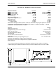
Generally, for in-building applications with one outside antenna and one or more indoor antennas, the
isolation due to spatial separation and the structure itself is adequate. It is always best to measure the
actual isolation under worst case conditions, if possible. The most direct way to measure the isolation is
to inject a known signal into one antenna, and measure the coupled signal at the other antenna. This
should be done across the applicable bandwidth to account for the frequency dependency of standing
waves.
4
4
8
8
7
7
5
5
0
0
D
D
o
o
n
n
o
o
r
r
A
A
n
n
t
t
e
e
n
n
n
n
a
a
S
S
e
e
r
r
v
v
i
i
c
c
e
e
A
A
n
n
t
t
e
e
n
n
n
n
a
a
(
(
s
s
)
)