
User Manual


USER’S MANUAL SERIES 48750 RF REPEATER
7 120556
INSTALLATION PROCEEDURE
Review this entire manual
Do not apply power until antennas have been connected to botht eh base and service area ports
!
Install donor antenna, aligned with desired base site and measure base signal strength.
The 48750 has sufficiniet filtering to prevent undesired signals from causing interference, however, it
is best to use a directional donor antenna to reduce the chance for interfernece by directing the mobile
signals only towards the desired donor base site.
The 48750 will work with a wide range of RF input signal levels. Ideal levels on the down link are in
the range of –60 to –70 dBm. These levels will provide the maximum output power while not causing
significant ovedrive.
!
Connect the donor antenna to the 48750 via 50 ohm coaxial cable.
Size and type of cable are a matter of choice. Typically ½” Flexwell foam coax is used, plenum rated
for inside buildings and work areas. However, 7/8
th
cable may be used to reduce the longitudinal loss.
½’ or smaller superflex cables are easier to install but have higher longitudinal loss.
!
Install service area antenna(s).
Determine the location and type of service area antennas is part of the distribution system design.
Generally it is desired to minimize the amount of coax that has to be installed. However, in buidlings
with extensive obstructions it may be neccesary to install several service area antennas For assistance
with antenna placement contact RFS Applications Engineering. Observe MPE cautions when
determining the type and location of all antennas (see section 1)!
!
Connect service antenna(s) via 50 ohm coaxial cable
Multiple service area antenna(s)/radiating cable runs may be connected the 48750. Splitters and taps
may be used to accommodate unique distribution systems.
!
Mount the 48750 Repeater upright, make sure there is sufficient space above and below the unit to allow
air to flow through the heat sink. Check to make sure the AC power cord can reach the power source.
Also provide adaquet bending room for the coxial cable.
!
Connect 50 ohm cables – donor antenna to “Base”, service antenna(s) to “Service”
!
Connect AC power to the 48750 and observe power and fault lights
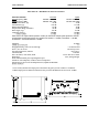
AC / DC POWER
AC power is supplied through a standard 3-wire male plug connected through a standard IEC-320 plug.
Connect this plug to any standard 3-wire 120 VAC outlet. A 5 x 20 mm, 3.15 amp fast blow fuse is used
to cut power in the event of a severe AC fault. A 5 amp mini ATO fuse is used between the 28 VDC
from the power supply and the control board which distributes the power to all components. This is
located on the control board.
WARNING:
ALWAYS REMOVE POWER BEFORE CHECKING OR CHANGING FUSES.
120 VAC can be lethal.
Always unplug
the amplifier before servicing the interior.
Never insert
conductive objects into any opening.
Do not remove or probe
under the plastic safety cover over the AC
terminals of the 24 VDC power supply.
Always use
a standard 3-wire electrical outlet with safety ground
for AC power.