
User's Manual


User Handbook L-RU Revision C
CONFIDENTIAL
PROPRIETARY
Reg. No.: User Handbook 1100182-C.DOC Page 8 of 29
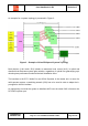
An example for a system topology is presented in Figure 3.
Figure 3 – Example of ClearFill
®
Space1 System Topology
Both devices (L-MU and L-RU) include an automatic level control (ALC) in uplink and
downlink that eliminates system gain variation, regardless of optical loss guarantying opti-
mised system performance under minimised installation effort.
The interface to the BTS / Node B or an Off-Air Repeater is the master unit. In case of a
multi-operator system a combining network (POI) has to be used in order to adapt the in-
put signal to the MU interface.
An opportunity to extend the system to distribute WiFi over the same DAS is foreseen via
RFS WiFi injection port.
L-RU
L-RU