Triple Trunking Handheld Radio Scanner 20-164 Thank you for purchasing your Triple Trunking Handheld Radio Scanner from RadioShack. Your scanner scans conventional frequencies and trunked systems. Please read this user’s guide before installing, setting up and using your new scanner. What’s Included Scanner Antenna Belt Clip Non-rechargeable Battery Holder Rechargeable Battery Holder Preprogrammed Frequency Addendum User’s Guide www.radioshack.
Contents Your Scanner...................................4 T Connecting the Antenna...........................5 Attaching the Belt Clip.............................5 Powering Your Scanner.............................6 Headphones and Speakers.......................9 Keytones and Keylock............................10 Backlight and Contrast...........................10 Squelch and Attenuator..........................11 Delay.....................................................13 Scanner Setup................
Contents Trunking Setup..............................32 Defining a Trunking Bank...................... 32 Trunking Modes.....................................33 Motorola Trunking Setup........................33 EDACS Trunking Setup............................36 LTR Trunking Setup.................................37 Searching for Talk Group IDs..................38 Saving a Talk Group ID...........................38 Deleting Talk Group IDs..........................39 Saving Trunking Channels....................
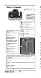
C Your Scanner VOLUME / OFF Squelch Headphones SCAN — Starts a scan. T a FUNC — Function 1 — Signal Stalker. PRI – Priority TEXT – Activates text buttons. PSE – Pause T t a c s c o MAN — Manually select a channel or enter a channel number. TRUNK — Accesses trunking functions. WX/ — Weather search and Skywarn. MODE – Changes receive mode. KEY/LIGHT – Keypad lock and backlight. TUNE – Enters Tune mode. ATT – Attenuator. – Navigates functions. SRCH – Search. 1-9 / A-Z– Numbers and letters.
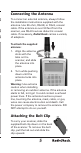
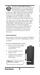
Connecting the Antenna To connect an external antenna, always follow the installation instructions supplied with the antenna. Use 50-ohm, RG-58, or RG-8, coaxial cable. If the antenna is over 50 feet from the scanner, use RG-8 low-loss dielectric coaxial cable. If necessary, RadioShack carries a variety of adapters. To attach the supplied antenna: 1. Align the antenna slots with the tabs on the scanner, and slide the antenna into place. 2. Turn while pushing down until the antenna locks into place.
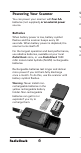
Powering Your Scanner You can power your scanner with �������� four AA batteries (not supplied)����������������������� , or an external power source. T 1 2 Batteries When battery power is low, battery symbol flashes and the scanner beeps every 30 seconds. When battery power is depleted, the scanner turns itself off.
, To install batteries: 1. Slide open the battery compartment cover on the back of the scanner. 2. Place 4 AA batteries into the correct battery holder matching polarity symbols (+ / -): • Black – Alkaline (non-rechargeable) • Yellow – Rechargeable. 3. Place the battery holder into the battery compartment and replace the cover. To charge batteries: 1. Install rechargeable batteries. 2. Connect an external power source to the PWR DC 9V jack. Using the scanner while charging will increase charge time.
The EPA certified RBRC© Battery Recycling Seal on the nickel-cadmium (Ni-Cd) battery indicates RadioShack voluntarily participates in an industry program to collect and recycle these batteries at the end of their useful life, when taken out of service in the United States or Canada. The RBRC program provides a convenient alternative to placing used Ni-Cd batteries into the trash or the municipal waste stream, which may be illegal in your area.
m If you use an external power source for regular operation, install alkaline batteries for emergencies. Rechargeable batteries will selfdischarge, even when not used, and could have no usable power. Caution: You must use a Class 2 power source that supplies 9V DC and delivers at least . 400 mA. Its center tip must be set to positive and its plug must fit the scanner’s PWR DC 9V jack. Using an adaptor that does not meet these specifications could damage the scanner or the adaptor.
Keytones and Keylock The scanner sounds a tone each time you press a key. To prevent accidental changes, you can lock the keypad. T 1 2 T To set the keytone: 1 1. Turn on the scanner. “Multi-system Trunking Scanner” appears. 2 2. While “Multi-system Trunking Scanner” appears, press 1 to turn on the keytone or 2 to turn it off. 3 To lock the keypad: 1. Press FUNC then KEY/LIGHT. “Key locked” appears briefly and the keypad is locked.
s g To turn on the backlight: 1. Hold down LIGHT until the light turns on. 2. To turn off the backlight, press LIGHT. To change the backlight mode: 1. Turn on the scanner. “Multi-system Trunking Scanner” appears. 2. While “Multi-system Trunking Scanner” appears, press LIGHT. 3. Press or to select a backlight mode and duration (seconds). Normal Keypress Ignore 3 K3 I3 5 K5 I5 10 K10 I10 20 K20 I20 4. Press ENT. To change the display contrast: 1. Press MAN. 2. Press FUNC then 9. 3.
If you set the squelch precisely at the threshold where the hissing sound stops, the scanner may pick up unwanted, partial, or very weak transmissions. To prevent this, most users prefer a position a bit past the threshold. With the attenuator on, the scanner might not receive weak signals. You can reduce interference using two attenuator modes: • Global – (Default) The attenuator setting is applied to all channels, bands, or groups. • Normal – Lets you set the attenuator in each channel, band, or group.
s Delay Some conversations might take several seconds between transmissions. To avoid missing a reply, a delay is automatically set for each channel. The scanner stops for 2 seconds after a transmission stops before it resumes scanning or searching. To turn the delay on / off: 1. Press ./DELAY. DLY appears if the delay is on. 2. To turn on the delay, press ./DELAY again. “dly” appears if the delay is off. Scanner Setup A frequency, expressed in kHz or MHz, is the tuning location of a station.
CT – FM transmissions with Continuous Tone Coded Squelch System (CTCSS) 6 DC – FM transmissions with Digital Coded Squelch (DCS) 7 MO – Motorola Trunking System ED – EDACS Trunking System LT – LTR Trunking System If you change the receive mode using MODE key, the scanner shows the receive mode for small caps (ex. fm, am, ct, or dc). If you want to change the default setting, press FUNC then press MODE. 8 Defining a Channel Go to www.radioreference.com for the latest frequency references.
e y 6. If necessary, press MODE to change the receiving mode. 7. Press ENT. If the frequency is already stored in the bank, “Dupl.Freq. ChXXX” appears. To copy the duplicate frequency anyway, press ENT or press CL to cancel. If you made a mistake in Step 5, “Invalid Freq.” briefly appears and the scanner beeps when you press ENT. Go back to step 5 again. 8. Press MAN again. M and the bank and channel number appear. For information about adding text tags to a channel or bank, see “Text Tags” on Page 44.
es If the frequency is already stored in the bank, “Dupl.Freq. ChXXX” appears. To copy the duplicate frequency anyway, press ENT or press CL to cancel. 7. Press MAN. Deleting Saved Frequencies T 1 To delete a saved frequency: 2 1. Press MAN. 3 2. Use the number keys to enter the frequency’s channel number. 4 3. Press MAN. 4. Press PGM. M changes to P. 5 5. Press FUNC. 6 6. Press CL. “0.0000” appears. To delete all saved frequencies in a bank: 1. Press PGM. M changes to P. 2. Press FUNC. 6 3.
transmissions operate independently of each other. Your scanner will not decode digital voice transmissions for CTCSS or DCS channels. Use FM mode for mixed analog and digital voice transmissions. To define a channel’s CTCSS or DCS code: 1. Press PGM. M changes to P. 2. Navigate to the channel. 3. Enter a conventional frequency. 4. Press MODE until the desired mode (CT or DC) appears with the default search code value. 5. Press FUNC, then MODE. 6. Use the or to select the desired CTCSS or DCS code.
The application software is also available online at www.starrsoft.com and www.scancat.com. 2 To clone the scanner data: 1. Turn on both scanners. PC/IF — PC interface cable for use with your computer. S T 1 2. Connect the connecting cable to each scanner’s PC/IF jack. ** CLONE MODE ** appears. 3. Press . “Confirm to send data?” appears. 4. Press 1 to send the data to the other unit or press any other key to cancel. 5. To exit the clone mode, remove the cable.
display. 2. To turn off Seek Search, press FUNC then 7 again. “Seek Search OFF” appears briefly. Search Banks To search preprogrammed search banks: 1. Press SRCH repeatedly to select a bank. Bank Band SR0 Marine SR1 CB SR2 FRS/GMRS/MURS SR3 Public Safety SR4 Aircraft SR5 Amateur Bands SR6 Railroad SR7 Limit search (User changeable) For SR0-SR2, you can directly select a channel or search through the band. SR3 to SR5 banks contain several groups.
To search banks SR0-SR2: 1. Press SRCH repeatedly to select SR0, SR1, or SR2. 2. To search the entire band, press FUNC then SRCH. “MAN” (Manual select) or “SRCH” (searches through the band) appears. The scanner starts searching while “SRCH” appears on the display. When the scanner finds an active frequency, it stops searching. Press FUNC then SRCH again to return to the previous mode. 3. To select a channel while “MAN” appears on the display, press a channel number or use or .
. n f frequency that is the closest step increment to the correct center frequency. To activate Zeromatic: 1. Press FUNC then 0. “Zeromatic ON.” appears briefly, then ZM appears. 2. To turn Zeromatic off, press FUNC then 0 again. “ZM” changes to “zm.” Programming a Search Range To program the search range of Bank SR7: 1. Repeatedly press SRCH to select SR7. 2. Press PGM then SRCH. “Enter SR7 Search Range Limits” appears. L blinks for the lower-limit of the range. 3.
advantages over typical portable frequency counters. T Signal Stalker II is more sensitive than portable frequency counters and will detect transmissions at a greater distance. Signal Stalker II rapidly searches the RF spectrum in 1 MHz segments. If it detects a signal, Signal Stalker II searches in finer steps until the signal source is found.
To use Special Signal Stalker II: 1. Press FUNC. 2. Use or to select “Sp. Stalker” appears for Special Signal Stalker II. 3. To turn off Special Signal Stalker II, press FUNC and then or again. Locking Out Frequencies When you lock out frequencies during a search, the scanner continues searching, but ignores the locked out frequencies. You can lock out up to 50 frequencies in each bank. If you try to lock out more, “L/O Memory Full!” appears.
2. Press FUNC then L/OUT. The first lockedout frequency and lockout list appear. If the search bank has no locked-out frequencies, “No Lockout” appears. 3. Press or to review the list. The current position and the total locked-out number also appear as “Lockout XX of YY.” (Example: Lockout 10 of 30.) 4. (Optional) To unlock a frequency, select the frequency then press CL. 5. Press FUNC then L/OUT again to exit. To unlock all frequencies in a search bank: 1. Press SRCH. 2. Select the search bank. 3.
t y k Scanning Scanning sequentially checks all saved channels for activity. You must save frequencies into channels to scan. The scanner does not scan empty channels or unsaved frequencies. You can increase the scanning speed by locking out channels with continuous transmissions, such as a weather channel or turning off entire banks. Turning off a bank prevents the scanner from scanning any channels within the bank. You cannot turn off all banks. There must be at least one active bank to scan.
3. Press L/OUT. On the display, “lo” changes to “LO.” T 4. To unlock a locked-out channel, press L/ OUT again. 2 1 To review all locked out channels: 1. Press MAN. 2. Repeatedly pressing FUNC and then L/OUT to view each locked-out channel. 3. To unlock a channel, press L/OUT. “LO” changes to “lo.” 4. When you finish reviewing locked-out channels, press MAN. You can manually select any channel in a bank, even in turned-off banks.
. . k To make an existing channel a Priority channel: 1. Press MAN. 2. Use the number keys to enter the bank and channel number. The Priority channel cannot be a trunking channel (MOT, ED, or LTR). 3. Press MAN. 4. Press FUNC, then hold PRI until the display blinks. To modify the Priority channel: 1. Press PGM. 2. Press PRI. 3. Use the number keys to enter the frequency. 4. Press ENT. If the frequency is incorrect, “Invalid Freq” appears briefly.
the Priority channel only if the scanner detects a weather alert. 4 To perform a weather scan: Press WX. Your scanner scans through the weather bands then stops on the next available weather broadcast. To program a weather channel into priority channel: 5 1. Press WX. 2. Select the weather channel. 3. Press FUNC and then PRI. SAME Standby Mode SAME alerts include FIPS codes to identify areas, established by the US Census bureau.
a a 4. Use the number keys to enter the FIPS code. The format of a FIPS code is: Subdivisions State Code County Code 0-9 01-50 XXX (0=entire area) (00=all states) (000=all counties) Example: 048439 (0=All; 48=Texas; 439=Tarrant County) 5. (Optional) To label the code, press TEXT and use the letter buttons to enter text. 6. Press ENT to store the code. Repeat this process to program additional FIPS codes. 7. Press L/OUT to lock out or enable specific FIPS entries. 8.
To enter SAME standby: T 1. Press FUNC, and then WX. The scanner will H monitor the selected weather radio station for alerts with FIPS codes that match the codes you entered in the FIPS entry table. 2. To exit SAME standby, press FUNC, and then WX. The scanner searches the weather frequencies while SAME standby mode when squelch is off. If p M W s To test the weather alert: 1. Press WX. Your scanner scans through the weather bands. 2. Set the Squelch to the lowest setting so that you hear static.
t ” To use Skywarn: Hold the Skywarn button ( ). “SKY” appears. If the skywarn channel is empty, “Not programmed” appears. Monitoring When monitoring, the scanner remains on a single channel. Your scanner features a power save circuit that allows the scanner to “sleep” briefly while waiting for a call on a monitored channel. To monitor a channel: 1. Press MAN. 2. Use the number keys to enter the channel number and press MAN. To find a frequency to monitor: 1. Press TUNE.
To set a default tuning frequency: 1. Press MAN. 2. (Optional) Use the number keys to enter the frequency number. 3. Press FUNC, then TUNE. The scanner saves the frequency. For example, if you save 145.31000 MHz, when you press TUNE, the scanner starts tuning at 145.31000 MHz. Trunking Setup Instead of transmitting on a specific frequency, trunking systems choose one of several frequencies during a 2-way radio transmission and simultaneously transmit a Talk Group ID that identifies the 2-way radio user.
s g g Trunking Modes In Closed mode, the scanner stops only on transmissions with saved and unlocked Talk Group IDs. This lets you focus a scan on the frequencies you have identified, ignoring other transmissions. In Open mode, the scanner stops for transmissions on any unlocked channel. This lets you search for Talk Group IDs that you can then save. While scanning, “–” appears for Closed mode and “+” appears for Open mode under the channel storage bank’s number.
Fleet Maps For Motorola Type I and hybrid systems, you must program a fleet map before saving Talk Group IDs. 6 7 To program a fleet map: 1. Press PGM then TRUNK. B 2. Press FUNC, then press or to select the bank. T t b t ( b f 3. If necessary, repeatedly press MODE to select “Motorola.” 4. Press FUNC, then press 8. “Size Code Setting” appears, with Block 0 selected. 5. Enter the size code for Block 0, supplied with the Type I system information, or try one of the following common fleet maps.
For Motorola Type II, enter 15. 6. Press ENT. The next block appears. 7. Repeat steps 5-6 for each block. If you make a mistake, press CL and enter the correct size code. Base and Offset Frequencies To receive Motorola VHF and UHF system transmissions, you must program applicable base and offset frequencies. In the 800 MHz trunking band, you can select a base frequency (normal or offset), but in the 900 MHz trunking band, you do not need to set the base frequency.
6. If necessary, use the number keys to enter a new Offset frequency and press ENT. The S in Step blinks. If you try to program an offset frequency in the UHF-Hi bands (806-960 MHz), the scanner ignores the entry. 7. While the S in Step blinks, repeatedly press or to select the step number: 5.0, 6.25, 10.0, 12.5, 15.0, 18.75, 20.0, 25.0, 30.0, 31.25, 35.0, 37.5, 40.0, 43.75, or 50.0 kHz, then press ENT. 8. Press PGM. UHF-Hi (806-960 MHz) To program 800 MHz Motorola trunking: 1.
Group ID data on a dedicated control channel. Scanning requires clear reception of the control channel at all times, so EDACS systems generally have a smaller usable area. You can manually select the data channel, but an external antenna can greatly improve EDACS scanning. If you are programming frequencies for an EDACS sysstem, you must store them in the Logical Channel Number order (usually listed as LCN#).
Searching for Talk Group IDs If you tune the scanner to an active Motorola control channel, the Motorola System ID and the approximate control channel message decode success rate appears. This helps you identify the system and the reception quality. When the scanner decodes control channel data from a Motorola system, COTRL appears on the display. To search for Talk Group IDs: T 1 2 3 4 5 1. Set the bank to Open mode. 2. Press SCAN. The scanner scans through all unlocked channels in the active banks.
a To define a Talk Group ID: 1. Press PGM, then press TRUNK to enter the ID program mode. 2. Press FUNC, then use or to select a bank. 3. Repeatedly press MODE to select a trunking mode (Motorola, EDACS, or LTR). 4. Repeatedly press TRUNK to select the subbank. 5. Press or to select the location where to store the Talk Group ID. 6. Use the number and decimal point keys to enter the Talk Group ID: For ED Talk Group IDs, you can enter either a decimal or AFS code.
To delete a Talk Group ID: 1. Press PGM then TRUNK. 2. Press FUNC, or to select ID memory. 3. Press FUNC then CL. To delete ALL talk group IDs in a bank: 1. Press PGM. 2. Press TRUNK to enter a Talk Group ID memory mode. 3. Select a Talk Group ID bank using FUNC, or . 4. Press FUNC then 6. “Clear entire list? Press 1 to clear all, any other key aborts” appears. 5. To clear the Talk Group IDs, Press 1. To cancel the deletion, press any key except 1.
. Trunked modes (MO, ED, and LT) can only be selected for frequencies above 137 MHz that use trunking operations. For information about adding text tags to a channel, see “Text Tags” on Page 44. Trunk Scanning In each bank, you can mix conventional channels and frequencies in a bank. However, you can scan only one trunking mode at a time, either EDACS, Motorola, or LTR. To focus on trunk scanning, during a normal scan, you turn off banks that contain only conventional channels.
For EDACS and Motorola (above 406 MHz range), the scanner monitors the control channel between each transmission to identify talk groups. For some Motorola (under 512 MHz range) and LTR systems, the scanner uses the subaudible data sent with each transmission to identify talk groups. Trunking Delay T 1 2 You can set a Talk Group ID delay separately from the channel delay. When active, the scanner checks the Talk Group ID for the delay time when a transmission ends.
z d s manually select the ID memory, and press L/OUT. LO changes to lo. You cannot clear all lockouts from a talk group at the same time. To review locked-out Talk Group IDs: 1. Press PGM then TRUNK. 2. Press FUNC. Then L/OUT. The first locked out ID appears. If the ID memory bank has no locked-out ID, you hear the low beep tone. 3. Press or to scroll through the list. 4. Press PGM to exit. Turning Off Sub-Banks To turn off a sub-bank: 1. Press TRUNK repeatedly to select the desired sub-bank. 2.
Talk Group ID Hold You can set your scanner to follow a trunking signal that you want to track during scanning. 2 To set Talk Group ID Hold: 1. While the scanner is stopped on a voice channel (VC appears), hold down TRUNK until “ID hold ON” appears. When the scanner receives a transmission, the “S” on the display changes to “H.” 2. To release ID hold, press SCAN or TRUNK. 3 Scanner Maintenance • Handle the scanner carefully; do not drop it.
• Press MAN. • Enter the bank and channel number. • Press PGM. M changes to P. 2. To define a text tag for a Talk Group ID: • Press PGM. • Press TRUNK. • Press FUNC then or to select the desired bank. • Press TRUNK to select the desired subbank. • Press or hold down or to select the desired group ID. 3. To define a text tag for a bank: • Press PGM. • Press FUNC then press bank number. “Bank X (0 through 9) selected” appears. 4.
To display the Talk Group ID: 1. If the scanner displays the text tag for a transmission, press TEXT. The ID code appears. 2. Press TEXT again to cancel. Troubleshooting Problem Solution The scanner is not working at all. Be sure the adaptor’s barrel plug is fully inserted into the PWR DC 9V jack. The center tip of the adaptor’s barrel plug must be set to positive. Cause: The AC or DC adaptor might not be connected. The batteries might be dead or need to be recharged.
Problem Solution The scanner does not Check the antenna. receive any stations or reception is poor. . Check the squelch.. Cause: . Antenna might not be Check the Attenuator.. . connected correctly. Turn the scanner off Squelch setting might then on again, or initialize the scanner. be too sensitive causing it to pick up unwanted, partial or weak transmissions. Antenuator might be on so your scanner might not receive weak signals. The scanner might need to be initialized.
Problem Solution Error message appears when trying to upload or download from a computer. Download and install the “Windows XP Driver to resolve PC connection error” file from your scanner’s Product Support Cause: page or the Software Your computer is using Download page on . Windows XP and does www.RadioShack.com. not have the necessary Then make your USB cable driver. connection and try again. Be sure the correct COM port is selected in device manager.
y Initializing the Scanner If the scanner’s display locks up or does not work properly after you connect a power source or install batteries, you might need to initialize it. Caution: This procedure clears the scanner’s memory. Initialize the scanner only after trying all other methods to correct issues. To initialize the scanner: 1. Turn off the scanner, then turn it on again. “Multi-system Trunking Scanner” appears. 2. While “Multi-system Trunking Scanner” appears, press 0. 3. Press 1. 4. Press ENT.
Scanning Legally Your scanner covers frequencies used by many different groups including police and fire departments, ambulance services, government agencies, private companies, amateur radio services, military operations, pager services, and wireline (telephone and telegraph) service providers. It is legal to listen to almost every transmission your scanner can receive. However, there are some transmissions you should never intentionally listen to.
f w u s by traveling to the scene of an incident without authorization. We encourage responsible, legal scanner use. FCC Notice This equipment has been tested and found to comply with the limits for a scanning receiver, pursuant to Part 15 of the FCC Rules. These limits are designed to provide reasonable protection against harmful interference in a residential installation.
References S R Appendix A: Glossary Frequency – The signal (expressed in MHz) used by broadcasting radios. To find active frequencies, you can use frequency guides available from your local RadioShack store, frequency lists posted on the Internet, or your scanner’s search function. Bank – A storage unit for a group of channels. A channel contains one frequency, and a bank can hold up to 100 channels. Channel – A programmable memory locations for a single frequency.
A n e Search bank: SR0 Marine band Receive mode: FM Ch. Freq. (MHz) Ch. Freq. (MHz) Ch. Freq. (MHz) 01 156.0500 21 157.0500 72 156.6250 05 156.2500 22 157.1000 73 156.6750 06 156.3000 23 157.1500 74 156.7250 07 156.3500 24 157.2000. 161.8000 77 156.8750 08 156.4000 25 157.2500. 161.8500 78 156.9250 09 156.4500 26 157.3000. 161.9000 79 156.9750 10 156.5000 27 157.3500. 161.9500 80 157.0250 11 156.5500 28 157.4000. 162.0000 81 157.0750 12 156.
Ch. Freq. (MHz) Ch. Freq. (MHz) Ch. Freq. (MHz) 01 26.9650 15 27.1350 29 27.2950 02 26.9750 16 27.1550 30 27.3050 03 26.9850 17 27.1650 31 27.3150 04 27.0050 18 27.1750 32 27.3250 05 27.0150 19 27.1850 33 27.3350 06 27.0250 20 27.2050 34 27.3450 07 27.0350 21 27.2150 35 27.3550 08 27.0550 22 27.2250 36 27.3650 09 27.0650 23 27.2550 37 27.3750 10 27.0750 24 27.2350 38 27.3850 11 27.0850 25 27.2450 39 27.3950 12 27.1050 26 27.
Search bank: SR3 Public Safety band Receive Mode: FM, CT, or DC Freq. (MHz) Step. (kHz) Group 0 Freq. (MHz) Step. (kHz) Group 2 33.420-33.980 10 453.0375-453.9625 6.25 37.020-37.420 10 458.0375-458.9625 6.25 39.020-39.980 10 460.0125-460.6375 6.25 42.020-42.940 10 462.5500-462.7250 6.25 44.620-45.860 10 465.0125-465.6375 6.25 45.880 467.5625-467.7125 6.25 45.900 Group 3 45.940-46.060 10 764.003125-766.996875 3.125 46.080-46.500 10 773.003125-775.996875 3.
Group Frequency (MHz) Step (kHz) 2 138.000-143.9875 12.5 148.000-150.7875 12.5 225.000-379.975 25 380.000-400.000 12.5 3 D Search bank: SR5 Amateur band Receive mode: FM, CT, or DC Group Frequency (MHz) Step (kHz) 0 28.0000-29.7000 5 1 50.0000-54.0000 5 2 144.0000-148.0000 5 3 222.0000-224.9950 5 4 420.0000-450.0000 5 5 902.000-927.9875 12.5 6 1240.0000-1300.0000 6.25 Search bank: SR6 Railroad Receive mode: FM, CT, or DC Frequency (MHz) Step (kHz) 159.810-161.5650 7.
85.4 Hz 118.8 Hz 162.2 Hz 192.8 Hz 241.8 Hz 88.5 Hz 123.0 Hz 165.5 Hz 196.6 Hz 250.3 Hz 91.5 Hz 127.3 Hz 167.9 Hz 199.5 Hz 254.
A PubSafety Band Freq. (MHz) Step. (kHz) Group 0 Freq. (MHz) Step. (kHz) M F fl Group 2 33.420-33.980 10 453.0375-453.9625 6.25 37.020-37.420 10 458.0375-458.9625 6.25 39.020-39.980 10 460.0125-460.6375 6.25 42.020-42.940 10 462.5500-462.7250 6.25 44.620-45.860 10 465.0125-465.6375 6.25 45.880 467.5625-467.7125 6.25 45.900 Group 3 45.940-46.060 10 764.003125-766.996875 3.125 46.080-46.500 10 773.003125-775.996875 3.125 Group 1 794.003125-796.996875 3.125 151.
Appendix E: Talk Group Format Motorola For Motorola Type I, enter the block number, fleet number and subfleet number. Fleet No. Subfleet No. XXX XX Example: XXX-XX Motorola Type II talk group IDs are 4- or 5-digit numbers, divisible by 16. EDACS Enter either a four-digit decimal number from 0001 to 2047. Agency Fleet Subfleet (AFS) numbers range from 00-001 to 15-157. The default EDACS setting is decimal. To use AFS format: 1. Press FUNC then 2. “AFS Format” appears briefly. 2.
Appendix F: Specifications Frequency Coverage: 25.000-26.960 MHz....................(in 10 kHz steps/AM) 26.965-27.405 MHz....................(in 10 kHz steps/AM) 27.410-29.505 MHz......................(in 5 kHz steps/AM) 29.510-29.700 MHz...................... (in 5 kHz steps/FM) 29.710-49.830 MHz.................... (in 10 kHz steps/FM) 49.835-54.000 MHz...................... (in 5 kHz steps/FM) 108.000-136.9916 MHz...........(in 8.33 kHz steps/AM) 137.000-137.995 MHz..................
1240–1300 MHz................................................ 0.7 uV AM: 25–54 MHz........................................................... 1 uV 108–136.99166 MHz............................................ 1 uV 137–174 MHz.................................................... 1.5 uV 216.0025–224.975MHz..................................... 1.5 uV 225-299.975 MHz................................................. 2 uV 300-405.975 MHz................................................. 3 uV 406–512 MHz............
Limited One-year Warranty This product is warranted by RadioShack against manufacturing defects in material and workmanship under normal use for one (1) year from the date of purchase from RadioShack company-owned stores and authorized RadioShack franchisees and dealers. For complete warranty details and exclusions, check with your local RadioShack store.