500 Series Industrial Ethernet Switches Installation Guide (Revised 8/4/2009) 1
Table of Contents Applicability....................................................................................................................................................... 3 Safety Warnings ................................................................................................................................................. 4 ATEX Installation Requirements………………………………………………………………………………6 Overview: 500 Series Industrial Ethernet Switches ...................................................
Applicability: This guide is applicable to Firmware Version 8 of the following products: 508TX-N 516TX-N 524TX-N Where: N 508FX2-N-XX-S 509FX-N-XX-S 517FX-N-XX-S 526FX2-N-XX-S 508FXE2-N-XX-YY 509FXE-N-XX-YY 517FXE-N-XX-YY 526FXE2-N-XX-YY = N for N-ViewTM = A for Advanced Management = Blank Otherwise XX = ST or SC and YY = -15, -40, -80 S = Standard Temperature Rating -20° C to 70° C = Blank for -40° C to 85° C Note: The firmware version can be seen on the power up banner on the serial console for a
Copyright, © N-TRON Corp., 2008 820 S. University Blvd., Suite 4E Mobile, AL USA 36609 All rights reserved. Reproduction, adaptation, or translation without prior written permission from NTRON Corp. is prohibited, except as allowed under copyright laws. Ethernet is a registered trademark of Xerox Corporation. All other product names, company names, logos or other designations mentioned herein are trademarks of their respective owners.
ENVIRONMENTAL SAFETY WARNING: Disconnect the power and allow to cool 5 minutes before touching. ELECTRICAL SAFETY WARNING: Disconnect the power cable before removing the enclosure top. WARNING: Do not operate the unit with the top cover removed. WARNING: Do not work on equipment or cables during periods of lightning activity. WARNING: Do not perform any services on the unit unless qualified to do so. WARNING: Do not block the air vents.
ATEX Installation Requirements 1. The conductor size of the phase conductor must be in the range of 0.05-2.08 mm2. 2. Field wiring must be suitable for a minimum of 110°C. 3. Ethernet Switches are intended for mounting in an IP54 enclosure in a pollution degree 2 environment. 4. Temperature testing of the Ethernet Switches was conducted on the switch itself in an 85°C aircirculating oven and resulted in a Temperature Code of T4. However, end-product temperature testing shall be considered. 5.
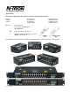
Overview: 500 Series Industrial Ethernet Switches The 500 Series Industrial Ethernet Switches support high speed layer 2 switching between ports. The 508TX (516TX)(524TX) is an affordable 8 (16)(24) port switch that is capable of auto negotiating 10/100 Mb and half/full duplex communications. The N-TRON 508TX (516TX)(524TX) is housed in a ruggedized steel enclosure, and provides 8 (16)(24) Category 5 compliant 10/100-BaseTX connections for high performance network design, and hub/repeater upgrades.
Key Features • • • • • • • • • • • • Full IEEE 802.3 & 100BASE-FX Compliance Full IEEE 1613 Compliance (Communications Networking Devices in Electric Power Stations) NEMA TS1/TS2 Compliance (Traffic Control Systems) American Bureau of Shipping (ABS) Type Approval (Maritime and Offshore Applications) Extended Environmental Specifications Support for Full/Half Duplex Operation LED Link/Activity Status Indication Auto-Sensing Speed and Flow Control Up to 2.
WARNING Never install or work on electrical equipment or cabling during periods of lightning activity. Never connect or disconnect power when hazardous gasses are present. Disconnect the power cable before removing the enclosure top. Do not operate the unit with the top cover removed UNPACKING Remove all the equipment from the packaging, and store the packaging in a safe place. File any damage claims with the carrier. CLEANING Clean only with a damp cloth. SERVICING No user serviceable parts inside.
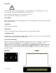
Front Pannel From Left to Right: LNK Link LED for Fiber Optic Port (only FX/FXE models) TX 100MB/s Fiber Optic TX Port (only FX/FXE models) RX 100MB/s Fiber Optic RX Port (only FX/FXE models) ACT Activity LED for Fiber Optic Port (only FX/FXE models) RJ45 Ports Auto sensing 10/100 BaseTX Connections Green LED lights when Power is connected NOTE: Each RJ45 data port has two LED’s located at the top or bottom of each connector.
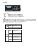
Applying Power (Side View) Unscrew & Remove the DC Voltage Input Plug(s) from the side header Install the DC Power Cables into the Plug(s) (observing polarity). Plug the Voltage Input Plug(s) back into the side header. Tightening torque for the terminal block power plug is 0.22 Nm/0.162 Pound Foot. All LED’s will flash ON Momentarily Verify the Power LED stays ON (GREEN). Note: Only 1 plug must be connected to power for minimal operation.
N-Tron Switch Grounding Techniques The grounding philosophy of any control system is an integral part of the design. N-Tron switches are designed to be grounded, but the user has been given the flexibility to float the switch when required. The best noise immunity and emissions (i.e. CE) are obtained when the N-Tron switch chassis is connected to earth ground via a drain wire. Some N-Tron switches have metal din-rail brackets that can ground the switch if the din-rail is grounded.
RJ45 Connector Crimp Specifications Please reference the illustration below for your Cat5 cable specifications: (Revised 8/4/2009) 13
Connecting the Unit For FX/FXE units, remove the dust cap from the fiber optic connectors and connect the fiber optic cables. The TX port on the FX/FXE models should be connected to the RX port of the far end station. The RX port on the FX/FXE versions should be connected to the TX port of the far end station. For 10/100 Base-TX ports, plug a Category 5E twisted pair cable into the RJ45 connector. Connect the other end to the far end station.
HyperTerminal The following configuration should be used in HyperTerminal: Port Settings: Data Bits: Parity: Stop bits: Flow Control: 9600 8 None 1 None Troubleshooting 1. Make sure the (Power LED) is ON. 2. Make sure you are supplying sufficient current for the version chosen. 3. Verify that Link LED’s are ON for connected ports. 4. Verify cabling used between stations. 5. Verify that cabling is Category 5E or greater for 100Mbit Operation. 6.
Software Configuration Command Line Interpreter With the ‘-A’ option, you can configure and/or query all the important parameters of an N-Tron 500 series industrial Ethernet switch using a command line interpreter. These functions may be accessed using the serial port (marked COM). To access the Command Line Interpreter (CLI), connect a PC serial port to the 500 Series V24 serial port and use HyperTerminal or equivalent.
Logging In (password protection) Access using the CLI is password-protected. You can log in as administrator to read and modify the 500 Series switch parameters. Note: The factory defaults admin password is admin. First press to access the Management Console Function. Login: enter username ‘admin’ and then press . Password: enter password ‘admin’, then press . (see section on user defined password) Example: Managing IGMP Snooping.....................
CLI Tree of Menus info (Show identification data) SYSTEM (Open system menu) nview • • aging • • • info1 info2 info3 info4 upwd restore SWITCH (Get information about N-View function) info (Get information about N-View) enable/disable (Enable/Disable N-View) (Aging Time for dynamically learned addresses) info (Get information about Aging) enable/disable (Enable/Disable Aging) config (Configure Aging) (Get information about system - ports 1->8) (Get information about system - ports 9->16) (Get
(SWITCH Sub-Menu Continued) igmp • • • • • filters • • • ports • • • • • • • • • • • (IGMP Snooping) info (Get information about IGMP Snooping) enable/disable (Enable/Disable IGMP Snooping) routers (Manage Router Port(s) for IGMP Snooping) • 'A' to Auto-detect plus manual, OR • 'M' for Manual only, OR • 'N' for None. rfilters (Manage Router Multicast Data Filters) query (Manage Query Generation) • 'A' to Auto query, OR • 'O' for query On, OR • 'F' for query oFF.
CLI Menus and Commands These commands are available at all menus (on a –A unit): Command / ? Description Returns you to the top of menu tree (available in every menu) Displays the current menu again (available in every menu) Comment Home function Refresh function Also: “u” or “U” = up one level in the menu tree \ = home Home Menu You can display all the other menus from the start menu.
System Menu Command nview Description Get information about N-ViewTM function. Set and get info on Aging Time for dynamically learned addresses Displays the current system status. (info for 508/9)(info1,2 for 516/7) (info1,2,3,4 for 524) (info1,2,3,4 for 526) Set a user defined password. Restores the defaults of the switch (complete reset). **Note: Power cycle is required when completed. aging info or info1, info2,... upwd restore Comment LINK Status. Rate, Flow, etc.
Aging Menu When enabled, the Aging Time for dynamically learned addresses can be set from 10 to 300 seconds. The default is 300 seconds, except it is 20 seconds for 508FX2 and 526FX2. Cycling power clears the learned addresses. Note: The configuration console is only available with –A models. On –N and basic (no dash) units, aging is enabled and uses the defaults above without the option for reconfiguration. Command info Description Displays the current Aging settings.
System Info System info provides information on each port, as shown in the example below. Note that this is real time status, and some parameters (such as Rate, Duplex, and Crossover) will oscillate if not linked and not forced. To see forced settings, go to switch/ports/info.
User Password The user password feature is optional and if used allows the user to create a password of 4 to 8 characters, including alphanumerics and special characters (20 hex through 7e hex). ‘Restore defaults’ restores the password to "admin", but note that if power has been cycled since a successful login one cannot get to ‘restore defaults’ without knowing the password. **Note: Power cycle is required when completed. The user password feature is available in firmware version 8.09 and subsequent.
Switch Menu Command Description mirror Enable, disable, and configure port mirroring trunking Enable, disable, and configure trunking qos Enable, disable, and configure port or tagged Quality of Service vlan Enable, disable, and configure Virtual Local Area Networks igmp Enable, disable, and configure IGMP Snooping filters Select traffic filter(s) ports Reconfigure Individual Port Parameters Port Mirroring Mirroring allows the data exchange at one port (mirrored port, or source port) to be m
Example of the Mirroring config screen: CLI\SWITCH\MIRROR>config Configure MIRROR Function For Port Mirroring, the Source Port is now: 17 Select Source Port [1...
MAC Based Trunking MAC Based Trunking provides performance and provides media redundancy. See an example below for multiple 508/509 Trunking configuration. Command info disable (or enable) config Description Display the current Trunking settings. Enables Disables Trunking Configure Trunking Comment Choice is opposite of current state Group1 and/or/nor 2 Notes on Trunking: • Mirroring overrides trunking (does mirror on the other trunk line). Can be used together carefully.
Example Configuration for 508/509 Trunking: Port 3 Port 5 Port 7 Port 1 508TX-A -or509FX-A Port 4 Port 6 Group 2 Activated If 509FX-A, Fiber (port 9) Port 8 Port 2 Port 3 508TX-A -or509FX-A Port 4 Port 5 Trunking Enabled Port 6 Port 7 Port 1 Port 3 Port 5 Trunk Pair Both Groups Activated 508TX-A -or509FX-A Trunking Enabled Group 1 Activated Port 7 (Revised 8/4/2009) Port 2 Trunking Enabled Trunk Pair Port 1 If 509FX-A, Fiber (port 9) Port 8 Port 2 Port 4 Port 6 If 509FX-A, Fiber (po
Example of the Trunking config screen: CLI\SWITCH\TRUNK>config Configure Trunking. Trunking is ENABLED. Trunk Group1 is now Active. Trunk Group2 is now Inactive. Enter: <(ESC)> to keep this configuration, 'A' to Activate both groups, 'D' to Deactivate both groups, '1' to activate Group1 and deactivate Group2, OR '2' to activate Group2 and deactivate Group1. Enter A, D, 1, 2, or <(ESC)> A Activated both groups.
Example of the Tagged QOS config screen: CLI\SWITCH\QOS>set_tag Configure Tagged QOS Threshold. The Tagged QOS threshold is now: 4 When an incoming 802.1p priority tag value is greater than or equal to this number, the incoming packet will be classified as high priority. Please Select Tagged QOS Threshold [0-7]: 6 The Tagged QOS threshold is now: 6 CLI\SWITCH\QOS> Example of the Port QOS config screen: CLI\SWITCH\QOS>set_port Configure Port QOS. Select higher priority ports.
VLAN A local area network (LAN) is a private network usually confined to one plant. Virtual LANs (VLANs) allow a single physical LAN to be partitioned into several smaller logical LANs. VLANs are an effective means of portioning a larger LAN into manageable subsets. VLANs restrict the broadcast domain, improve performance and security, and they are ideal for isolating industrial automation systems from IT systems while retaining the plant's structural wiring.
Tagged VLAN Tagged VLAN is in accordance with IEEE 802.1Q. When configuring each group: o choose VID ( 2-511 ranged on input) (except group1 is always VID=1) o choose member ports (any, all or none) o by port, choose if this is the primary VID for the port. o by port, for this group, choose if outgoing packets are untagged ( a port could tx untagged if one VID and tagged if another VID) When configuring untagged incoming packet handling: - Drop all untagged incoming packets, or which ports to do this on.
When VLAN is enabled, all ports are members of VID 1 by default. If you enter ‘group2’, for example, you’ll be asked to enter (in decimal) a VLAN ID (VID) in the range of 1 through 511. Then, you’ll be asked to enter the ports that are to participate in that tagged VLAN. Then, you’ll be asked if all these ports are to have that VID as their PVID or not. Then, you’ll be asked if you want outgoing packets to be untagged for all these ports or not.
Example of the Tagged VLAN config ( groupX ) screen, not taking default choices: This example below chooses only some (not all) group ports to have the group VID as their PVID, and outgoing packets to be untagged for some (not all) group ports. CLI\SWITCH\VLAN>group7 Configure Tagged VLAN Group 7. Enter VID or <(ESC)> to exit> 325 Enter ports to Join VLAN Group 7 (Example: '3,6,12,14'.
Example of tagged vlan info: CLI\SWITCH\VLAN>info Tagged VLAN is DISABLED. When enabled: Untagged pkts to these ports are discarded: 1 8 VLAN GROUP1 has VID= 1 and includes Ports: 7 8 9 10 11 12 13 14 15 16 GROUP1 outgoing pkts are untagged for ports: 7 8 9 10 11 12 13 14 15 16 VLAN GROUP2 has VID=215 and includes Ports: 2 6 17 GROUP2 outgoing pkts are untagged for ports: 2 6 17 VLAN GROUP7 has VID=325 and includes Ports: 1 2 3 4 5 6 17 GROUP7 outgoing pkts are untagged for ports: 1 6 There is more.
Tagged VLAN Example scenario: This example illustrates a case where all devices attached to the switch are VLAN unaware, except the ‘feed’ from another switch or router on port 1. All devices on this switch are in VLAN VID=4, which is unique in a topology that includes multiple switches. - port 1 accepts and sends only tagged VID=4 frames. (discards any other incoming - untagged or other tags not 4) (sends no untagged nor any other tags not 4) - the other ports ( 2 thru 17) send out only untagged frames.
Tagged VLAN Example scenario: ( continued from previous sheet) CLI\SWITCH\VLAN>info Tagged VLAN is ENABLED. Untagged pkts to these ports are discarded: 1 VLAN GROUP1 has VID= 1 and includes Ports: none GROUP1 outgoing pkts are untagged for ports: none VLAN GROUP2 has VID= 4 and includes Ports: all GROUP2 outgoing pkts are untagged for ports: 2 3 4 5 6 7 8 9 10 11 12 13 14 15 16 17 There is more. Press 'SPACE BAR' to continue, or escape to exit.
Port VLAN Port VLAN is accomplished entirely within the switch itself. All incoming frames can be untagged, or if tagged the tag will be replaced by the PVID (see explanation above). Incoming packets will use the (internal to the switch) PVIDs to determine group membership. All outgoing frames will be untagged. All unlearned packets will flood only to all group member ports. Multicast and Broadcast will go only to group members.
Example of the Port VLAN config ( groupX ) screen, not taking default choice for PVID: This example below chooses only some (not all) group ports to have the group VID as their PVID. CLI\SWITCH\VLAN>group4 Configure Port VLAN Group 4. Enter ports to Join VLAN Group 4 (Example: '3,6,12,14'.) Enter Port Numbers (or ESC to exit)> 1,2,3,4,5,6,7,8,9 Would you like all these ports to have PVID=4 ? Enter 'NO' or (YES): CLI>no Enter ports to have PVID=4 (Example: '3,6,12,14'.
Port VLAN Example scenario : ports 1,2,3 - control system (only communicate with each other and the 2 PC's) ports 4,5 - PCs (each communicate with all ports 1 thru 9) ports 6,7,8,9 office system (only communicate with each other and the 2 PC's) For example: TX 7 to 3 and no ports RX. Notice below,, the configuration step: “Would you like all these ports to have PVID=4 ? Enter 'NO' or (YES): CLI>no Enter ports to have PVID=4 (Example: '3,6,12,14'.
Port VLAN Example scenario: ( continued from previous sheet) CLI\SWITCH\VLAN>group4 Configure Port VLAN Group 4. Enter ports to Join VLAN Group 4 (Example: '3,6,12,14'.) Enter Port Numbers (or ESC to exit)> 1,2,3,4,5,6,7,8,9 Would you like all these ports to have PVID=4 ? Enter 'NO' or (YES): CLI>no Enter ports to have PVID=4 (Example: '3,6,12,14'.) Enter Port Numbers (or ESC to exit)> 4,5 CLI\SWITCH\VLAN>info Port VLAN is ENABLED. All outgoing frames will be untagged.
IGMP Snooping In factory defaults, IGMP Snooping is enabled, and the switch is Plug and Play for IGMP. IGMP snooping provides intelligent network support for multicast applications. In particular, unneeded traffic is reduced. IGMP Snooping is configured via the console and if enabled, then operates dynamically upon each power up and until entering escape to the console terminates it. Also, there can be manual only or manual and dynamic operation (as described below).
Example of entering manually selected routers in auto-detect plus manual: ( One does not have to manually enter anything for IGMP SNOOPING, unless accommodating non-IGMP devices.) Enter A, M, N , (or ESC to exit) > a For IGMP Snooping, router ports mode is auto. Manually Selected Router Port(s): none Automatically detected Router Port(s): none Would you like to change that ? Enter 'YES' or (NO): CLI> yes Enter ports to be router ports: Use commas to separate port numbers. (Example: '3,6,12,14'.
The query management function enables the switch to generate IGMP “Query” messages: never, always, or automatically. Example of Configure Query Generation screen: CLI\SWITCH\IGMP>query Configure Query Generation. Query mode is auto. Query Frame Source IP: 192.168.69.102. Enter: <(ESC)> to keep this configuration, OR 'A' to Auto query, OR 'O' for query On, OR 'F' for query oFF.
Example of an IGMP info screen (without cycling power, , SWITCH, IGMP, INFO): CLI\SWITCH\IGMP>info IGMP Snooping is ENABLED. When power is cycled: Query mode is auto. Query Frame Source IP: 191.23.12.15. Received Lower Query Frame Source IP: 10.10.10.5. For IGMP Snooping, router ports mode is auto.
Filters Note that these filters operate whether IGMP Snooping is enabled or not. These are egress filters. ‘General Broadcast’ frames have a Destination Address of all ones (FF FF FF FF FF FF). The default is that all ports receive General Broadcast. You can select which ports are to receive General Broadcast, but only if vlan is not enabled. At least twelve ( 16 on 524/526) ‘static filters’ are provided. You can use any, all, or none.
Example of the Filters sfilter screen: CLI\SWITCH\FILTERS>sfilter Enter 1, 2, 3, ... ,16, or <(ESC)> > Enter: <(ESC)> to cancel change and keep current configuration, or static multicast filter number (1 ->16). CLI> 1 Enter 12 digit Address (Ex. '01005e0a0a0a'), or all zeroes to disable the group. or [ESC] to Exit CLI> 01005e010100 Enter ports that are to receive on this multicast address: Use commas to separate port numbers. (Example: '3,6,12,14,22'.
First, the class D address must be known. While some of these class D addresses are well known (224.0.1.1 is used by NTP Network Time Protocol specified in RFC1119 for instance), the majority are defined when the application is activated. Often, the class D address is the originating host computer’s IP address. In most applications, the user has the option of choosing their multicast group address as a session is established.
Ports By default, the RJ45 ports are auto-sensing for speed, duplexing, and crossover or straight through wiring. When you select ANY ‘forced’ option, the auto-sensing for that port is disabled for all three parameters and the ‘remaining’ (unforced) options are set to 100 Mbits, Full Duplex, and straight through cabling. For example, if you select speed10 for port 2, then port 2 will be: speed10, full duplex, and straight through wiring.
Each time you select a forced port function (speed, duplex, or crossover) the ports you enter next are the complete new set of ports for that function. For example, if you enter ‘speed10’, then respond with only (no ports) to the prompt “Enter forced 10 Mb ports:”, then no ports in the switch will be forced to 10 Mb, regardless of prior history. ‘Link10h’ technically auto negotiates, but ‘advertises’ only 10 Mb and full duplex capability.
CLI\SWITCH\PORTS>link10h Enter ports to advertise 10Mb and half duplex: Use commas to separate port numbers. (Example: '3,6,12,14,22'.) Enter Port Numbers (or ESC to exit):12,13 CLI\SWITCH\PORTS> Example of the Ports filter screen: CLI\SWITCH\PORTS>filter The threshold for collision filter management is 10 collisions in 20 seconds. Would you like to change it ? Enter 'YES' or (NO): CLI> Enter ports to apply collision filter to: Use commas to separate port numbers. (Example: '3,6,12,14,22'.
500 Series Stacked Switches IGMP Multicast Limitations With Quality of Service (QOS) DISABLED, as in factory defaults out of box: To prevent IGMP Multicast congestion problems, the following rules should be followed for multicast frames of up to 256 bytes each: 1. IGMP Snooping should be enabled, as in factory defaults out of box, and other multicasting devices in the LAN should be compliant. 2.
With Quality of Service (QOS) ENABLED, which would have to be manually configured: To prevent IGMP Multicast congestion problems, the following rules should be followed for multicast frames of up to 256 bytes each, when QOS is enabled: 1. IGMP Snooping should be enabled, as in factory defaults out of box, and other multicasting devices in the LAN should be compliant. 2. No more than three stages of switches should be stacked if the bottom layer is composed of simultaneously multicasting devices.
Key Specifications (508TX) Switch Properties Number of MAC Addresses Aging Time Latency Min. Backplane Speed Switching Method 4,000 Programmable 2.2 µs 2.6Gb/s Store & Forward Physical Height: Width: Depth: Weight: Din-Rail: 2.3" 5.5" 3.5" 1.6 lbs 35mm Electrical Redundant Input Voltage: Input Current: Inrush Current: Input Ripple: 10-30 VDC 200 mA @ 24VDC (max current 0.5 A) 9.0 Amp/0.
Regulatory Approvals: Safety: UL 1604 (US and Canada) Hazardous Locations, Class I, Div 2, Groups A, B, C, D, T4A ATEX Zone 2, Category 3G, II 3G Ex nA IIC (DEMKO 03 ATEX 0316686U) IEC61010-1/EN61010-1 EMI: EMS: EN61000-6-4, EN55011 – Class A FCC 47 CFR, Part 15, Subpart B -Class A EN61000-6-2 EN61000-4-2 (ESD) EN61000-4-3 (RS) EN61000-4-4 (EFT) EN61000-4-5 (Surge) EN61000-4-6 (Conducted Disturbances) Conducted Low Frequency: IEC60533 Shock: Vibration: Cold: Dry Heat: Damp Heat: IEEE 1613 (250 mm) IEEE 1
Key Specifications (508FX2/FXE2) Switch Properties Number of MAC Addresses Aging Time Latency Min. Backplane Speed Switching Method Physical Height: Width: Depth: Weight: Din-Rail: 2.3" 5.9" 3.5" 1.7 lbs 35mm Electrical Redundant Input Voltage: Input Current: Inrush Current : Input Ripple: 10-30 VDC 380 mA @ 24VDC (max current 1.0 A) 8.5 Amp / 0.
Recommended Wiring Clearance: Front: 5" (12.7 cm) Side: 3" (7.
Key Specifications (509FX/FXE) Switch Properties Number of MAC Addresses Aging Time Latency Min. Backplane Speed Switching Method 4,000 Programmable 2.2 µs 2.6Gb/s Store & Forward Physical Height: Width: Depth: Weight: Din-Rail: 2.3" 5.5" 3.5" 1.6 lbs 35mm Electrical Redundant Input Voltage: Input Current: Inrush Current: Input Ripple: 10-30 VDC 260 mA @ 24VDC (max current 0.5 A) 8.5 Amp / 0.
Recommended Wiring Clearance: Front: 5" (12.7 cm) Side: 3" (7.
Key Specifications (516TX) Switch Properties Number of MAC Addresses Aging Time Latency Min. Backplane Speed Switching Method 4,000 Programmable 2.2 µs 2.6Gb/s Store & Forward Physical Height: Width: Depth: Weight: Din-Rail: 2.3" 7.4" 3.5" 1.9 lbs 35mm Electrical Redundant Input Voltage: Input Current: Inrush Current: Input Ripple: 10-30 VDC 400 mA @ 24VDC (max current 1.0 A) 7.0 Amp / 0.
Regulatory Approvals: Safety: UL 1604 (US and Canada) Hazardous Locations, Class I, Div 2, Groups A, B, C, D, T4A ATEX Zone 2, Category 3G, II 3G Ex nA IIC (DEMKO 03 ATEX 0316686U) IEC61010-1/EN61010-1 EMI: EMS: EN61000-6-4, EN55011 – Class A FCC 47 CFR, Part 15, Subpart B -Class A EN61000-6-2 EN61000-4-2 (ESD) EN61000-4-3 (RS) EN61000-4-4 (EFT) EN61000-4-5 (Surge) EN61000-4-6 (Conducted Disturbances) Conducted Low Frequency: IEC60533 Shock: Vibration: Cold: Dry Heat: Damp Heat: IEEE 1613 (250 mm) IEEE 1
Key Specifications (517FX/FXE) Switch Properties Number of MAC Addresses Aging Time Latency Min. Backplane Speed Switching Method 4,000 Programmable 2.2 µs 2.6Gb/s Store & Forward Physical Height: Width: Depth: Weight: Din-Rail: 2.3" 7.4" 3.5" 1.9 lbs 35mm Electrical Redundant Input Voltage: Input Current: Inrush Current: Input Ripple: 10-30 VDC 440 mA @ 24VDC (max current 1.0 A) 8.5 Amp / 0.
Recommended Wiring Clearance: Front: 5" (12.7 cm) Side: 3" (7.
Key Specifications (524TX) Switch Properties Number of MAC Addresses Aging Time Latency Min. Backplane Speed Switching Method 4,000 Programmable 2.2 µs 2.6Gb/s Store & Forward Physical Height: Width: Depth: Weight: 1.8" 19" 4.3" 3.7 lbs Electrical Redundant Input Voltage: Input Current: Inrush Current: Input Ripple: 10-30 VDC 720 mA @ 24VDC (max current 1.0 A) 9.5 Amp / 0.
Regulatory Approvals: Safety: UL 1604 (US and Canada) Hazardous Locations, Class I, Div 2, Groups A, B, C, D, T4A ATEX Zone 2, Category 3G, II 3G Ex nA IIC (DEMKO 03 ATEX 0316686U) EMI: EMS: EN61000-6-4, EN55011 – Class A FCC 47 CFR, Part 15, Subpart B -Class A EN61000-6-2 EN61000-4-2 (ESD) EN61000-4-3 (RS) EN61000-4-4 (EFT) EN61000-4-5 (Surge) EN61000-4-6 (Conducted Disturbances) Conducted Low Frequency: IEC60533 Shock: Vibration: Cold: Dry Heat: Damp Heat: IEEE 1613 (250 mm) IEEE 1613 (V.S.
Key Specifications (526FX2/FXE2) Switch Properties Number of MAC Addresses Aging Time Latency Min. Backplane Speed Switching Method 4,000 Programmable 2.2 µs 2.6Gb/s Store & Forward Physical Height: Width: Depth: Weight: 1.8" 19" 4.3" 3.7 lbs Electrical Redundant Input Voltage: Input Current: Inrush Current: Input Ripple: 10-30 VDC 720 mA @ 24VDC (max current 1.0 A) 13.1 Amp / 0.
Recommended Wiring Clearance: Front: 2" (5.
N-TRON Limited Warranty N-TRON, Corp. warrants to the end user that this hardware product will be free from defects in workmanship and materials, under normal use and service, for the applicable warranty period from the date of purchase from N-TRON or its authorized reseller.