
Specifications

Vanner Power Group
AutoThrottle Manual
- 4 -
Section 2 — Theory of Operation
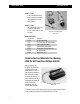
The solenoid of the 73-46 is a continuous duty, 12-volt utilizing internal dual coils. The first, a pull-in
coil, is designed for 12-volt intermittent duty (increasing engine RPM to high idle); while the second; a
hold-in coil is designed for continuous duty (maintaining high idle engine RPM). The solenoid plunger is
activated by the pull-in coil and bottoms in the solenoid instantly, then is held in this position by the
hold-in coil. If the solenoid is operated continuously with the plunger in an unseated position (the pull-in
coil operating) the solenoid will burn out in 15 to 30 seconds.
The function of the control module is to sense the brake switch and neutral safety switch. When the foot
brake is not depressed or when the vehicle gear shift is in park or neutral, the control module activates the
solenoid, causing it to pull in, and the cable to activate the throttle linkage thus increasing the RPM of the
engine. Conversely, when wither the foot brake is applied or the vehicle is put into gear, the control
module responds and signals the solenoid to release instantly allowing the engine RPMs to reduce to a
slow idle.
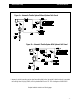
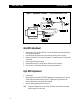
The wring circuit functions as follows. The red wire is the power input for the system. It is desirable to keep
this wire as short as possible using at least a 12 gauge wire. The white wire carries the power from the
control module to the solenoid. The white/red wire carries the signal from the brake switch to the control
module. When the brake pedal is depressed, the module then deactivates the solenoid causing the engine
RPMs to drop to low idle. The white/black wire of the control module picks up a ground signal from the
neutral safety switch. When the neutral safety switch is in park or neutral, the control module sees ground,
and signals the solenoid to energize thus increasing the RPMs to a fast idle. The reverse happens when the
neutral safety switch senses the vehicle being placed in gear. The ground is not seen and the signal is sent
to the control module, which causes the solenoid to deactivate. Whenever the solenoid energizes, the
system will draw high amperage for a split second (the time it takes the solenoid plunger to bottom out)
then will reduce to a minimum draw for as long as the solenoid is activated. It is done this way to reduce
the power required for operation and to get the most strength out of a relatively small solenoid.
Section 3 — Troubleshooting
The first thing to check is the cable (Aut-09) going to the throttle linkage. If the cable housing was melted
by the exhaust manifold or otherwise damaged to a point where the stainless steal cable is jammed in the
housing, the cable won’t work and must be replaced.
The rest of the troubleshooting involves the electrical circuits. First test the solenoid. With the engine OFF,
disconnect the white wire where it is connected to the positive (+) terminal on the solenoid (Aut 0-11).
Using a fused 50-amp jumper, apply (+) 12 volts though a 50A ammeter to the positive (+) terminal
of the solenoid. Be certain that the negative terminal of the solenoid is securely grounded. The solenoid is
operating properly if the plunger pulls in, (audibly bottoms out) and the ammeter reading is between 0.5
and 1.0 amps. You should observe a momentary surge of up to 45 amps before the needle settles at the