
Specifications

Vanner Power Group
AutoThrottle Manual
- 5 -
0.5 to 1.0 amp reading. If the plunger does not pull in, and you see a 0.5 10 1.0 am reading, the
solenoid is not functioning correctly and must be replaced. If the plunger does pull in and bottoms out, but
your amp reading is outside the above ranges, the solenoid is not functioning properly and must be
replaced. This completes the electrical test of the solenoid.
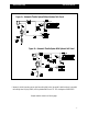
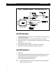
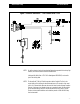
Connect the 50A ammeter, positive to the end of the white wire form the control module and negative to
the positive (+) terminal of the solenoid. Activate the Auto Throttle system either by turning the ignition
switch “on” or through an auto throttle auxiliary on/off-switch if one has been installed. If the system is
functioning normally, the solenoid may bottom. You must continue testing to confirm if all components are
operating properly. Using a voltmeter (meter negative connected to the chassis) connect meter positive,
first to the red wire from the control module. You should measure 12 volts on the red wire. If the reading is
less than battery voltage, then check the red wire circuit for a blown fuse, defective on/off switch, etc. Next
connect the meter positive to the white/black wire from the control module. The voltmeter should read less
than 2 volts. If the reading is 2 to 8 volts, there is a conflicting electrical circuit in the vehicle system and
we recommend that a double pole, double throw relay be installed in the neutral safety switch circuit to
isolate the two conflicting systems. If the reading is above 8 volts, you should check for an open neutral
safety switch condition, a broken white/black wire, etc. For the final volt meter test, measure the voltage
on the white/red wire; you should read not more than 2 volts. A reading exceeding 2 volts indicates an
incorrect connection of the white/red wire at the brake switch. This connection should be made on the
brake light side of the brake switch.
To test the brake disable, apply the brake; the ammeter should drop to zero. Release the brake and the
ammeter will reflect a momentary surge of up to 45 amps then drop back to 0.5 to 1.0 amps. If this test
fails, the problem is in the control module (Asm-43). Replace the module.
As a final check of the neutral safety switch circuit, secure the vehicle by setting the parking brake and
blocking the wheels. Activate the 73-46 (solenoid will bottom) with the engine OFF. Drop the gearshift
lever into drive. The solenoid should release. If it does not release It may be due to (1) a non-functioning
control module, (2) a misaligned or shorted neutral safety switch, or (3) a partial grounding of the white/
black wire through the vehicle’s normal wiring system. First, disconnect the white/black wire at the neutral
safety switch. If the solenoid disengages, the control module is functioning normally. If the solenoid
remains in a seated position, replace the control module. To check for a misaligned or shorted neutral
safety switch, refer to the manufacturer’s test procedures. If (1) and (2) check properly, then correct (3) by
installing a double pole, double throw relay circuit to isolate the two conflicting systems.