
Specifications

Radio Systems Millenium-D Digital Console Page 15
2.2.9 Analog/Digitalprogramming
Three-pin Jumper Z must be installed between the middle and upper pins in
the Millenium Digital console, on every channel. This communicates channel
on/off status to the console processor.
2.2.10 RemoteControlConnector
A 15-pin D connector is provided on the Six Channel Control Board for each channel to access all remote functions.
All control (input) functions are activated via a momentary pull-to-ground, except the “cough” function, which must be
held to +15V. All control output functions are open lines which go low when the function is activated. Lamp drivers are
current-sinking inputs.
Two modes of remote control functionality are available via recently supplied PROMS. These modes are selected via
the installation of jumper JU-213. In the default mode (JU-213 not installed,) remote control cue for IFB applications is
provided. With JU-213 installed, “Classic” remote controll functionality, indentical to previous PROM versions is pro-
vided.
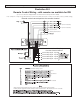
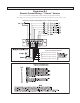
Refer to Illustration B-2 and B-3 for a pin-by-pin reference descriptions and wiring diagram.
Use the included 15-pin D connector ribbon extenders to plug in the mating D connectors external to the console, as
internal clearance for these connectors is not available inside the console.
2.2.11 OptionalRemoteControlBoard
Radio Systems’ optional Remote Board (RS Part # REMOTE) connects to the remote control connector and provides
the user with programmable relay interface for channel remote control outputs and opto-isolated input to channel on/off
and off lamp functions. Consult the interface option section for more details and pin-out and wiring diagrams.
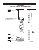
2.3 MonitorControlBoard
One monitor card (RS Part #10887) is installed on the right-hand side of the console front panel. It provides all monitor
and clock switching and logic functions.
The monitor board also provides eight uncommitted, illuminated momentary
switches for remote control of source equipment. These switches and LED’s
are connected to and read by the processor on the digital output board. The processor may
be set, via software screens, for various push-on / push-off momentary and switch interlock
states. The Eight Position Switches may also be programmed to control utility bus main/
alternate configuration switching. Consult the “Eight Position switches” page in the software
section of this manual for more information.
Connectors J-39 and J-43 on the digital output board are provided to interface with the console four source switcher
option board (RS Part # ROUTER) and console intercom board (RS Part # INTERCOM). Consult the interface option
section for more information.
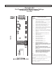
SeeIllustrationB-1,Pg16