
Specifications

Radio Systems Millenium-D Digital Console Page 2
Installation/Wiring/Operation ................................................................................................. 5
1.1 Console Placement ........................................................................................................ 5
1.2 Opening the Console ..................................................................................................... 5
1.3 Power Supply ................................................................................................................. 5
1.3.1 Installation ...................................................................................................................... 5
1.4 Wiring Access Layout .................................................................................................... 5
1.4.1 Audio Inputs................................................................................................................... 5
1.4.2 Audio Outputs ................................................................................................................ 5
1.4.3 Control ........................................................................................................................... 6
1.4.4 Audio Connectors .......................................................................................................... 6
1.4.5 Wiring Quick Connectors ............................................................................................... 6
1.4.6 Grounding and Shielding .............................................................................................. 6
1.5 Operation ....................................................................................................................... 6
1.5.1 Input Assignment .......................................................................................................... 6
1.5.2 Mic Use ......................................................................................................................... 7
1.5.3 Cue Circuitry ................................................................................................................. 7
1.5.4 Output Routing .............................................................................................................. 7
1.5.5 Utility Buses ................................................................................................................... 7
1.5.6 Mix-Minus via the “TEL” Bus .......................................................................................... 7
1.5.7 Monitor Amplifier Output Select .................................................................................... 7
1.5.8 Headphone Amplifier Output Select .............................................................................. 8
1.5.9 VU Meter Selection (six channel consoles only)............................................................ 8
1.5.10 Remote Control .............................................................................................................. 8
1.5.11 Eight Position Switcher .................................................................................................. 8
1.5.12 Console Clock Timer...................................................................................................... 8
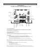
Illustration A-1 CT-2002 Console Clock/Timer/Master Clock ................................................................. 9
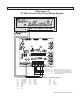
Illustration A-2 CT-2002 Console Clock/Timer Wiring Diagram ........................................................... 10
Illustration A-3 LED Meter Board with Talkback Microphone .............................................................. 11
Six Channel Control Board ................................................................................................... 12
2.1 Overview ...................................................................................................................... 12
2.2 Function Programming ................................................................................................ 12
2.2.1 Channel Power-Up Mode ............................................................................................ 12
2.2.2 Remote Control Options – by Channel ........................................................................ 12
2.2.3 Remote Control Options – by Input ............................................................................. 13
2.2.3.1 Pulse/Holding Remote Control..................................................................................... 13
2.2.3.2 Send Through of Remote On/Off Commands ............................................................. 13
2.2.4 Muting Buses ............................................................................................................... 13
2.2.5 Timer Reset .................................................................................................................. 13
2.2.6 Cue Options by Channel ............................................................................................. 14
2.2.6.1 Cue on Fader Detent ................................................................................................... 14
2.2.6.2 Auto Cue ...................................................................................................................... 14
2.2.6.3 Cue Defeat on Channel ON ......................................................................................... 14
2.2.6.4 Cue Exclusive .............................................................................................................. 14
2.2.7 Cue Options by Input .................................................................................................. 14
2.2.8 Off (Ready) Lamp Options .......................................................................................... 14
2.2.9 Analog/Digital programming ....................................................................................... 15
2.2.10 Remote Control Connector .......................................................................................... 15
2.2.11 Optional Remote Control Board................................................................................... 15
2.3 Monitor Control Board ................................................................................................. 15
Illustration B-1 Six Channel Control Board Jumper Settings ............................................................. 16
Illustration B-2 Remote Control Wiring (factory default with Cue for IFB) ........................................... 17
Illustration B-3 Remote Control Wiring (“Classic” Mode) .................................................................... 18
Six Channel Audio Mother Board ........................................................................................ 19
3.1 Input Connectors ......................................................................................................... 19
3.2 Input Configurations .................................................................................................... 19