
Specifications

Radio Systems Millenium-D Digital Console Page 25
Output Boards
4.0 Overview
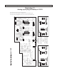
In the Millenium digital console two circuit boards provide all audio outputs and certain other related functions. The
two large circuit boards are mounted on top of each other and are located on the right-hand inside pan of the console.
The lower board provides most of the analog output functions and is identical to the circuit board utilized in Millenium
analog consoles. The upper board provides mostly digital functions. A metal shield mounts between the boards for in-
terference isolation. Trim pots on the lower board are accessible through holes with silk-screened legends in the upper
board. I/O connectors on the lower board can be accessed in the rear where the upper board is cut back.
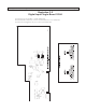
Millenium digital console output boards may be ordered factory equipped with either 5-pin removable barrier strip
connectors or RJ-45 style connectors. RJ-45 connectors are wired to the StudioHub+ audio standard. Both connectors
accommodate either mono or stereo balanced or unbalanced analog connectivity or balanced AES-EBU or unbal-
anced S/PDIF connections. Illustrations D3 and D4 show the location and pin-outs of these various audio connectors.
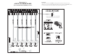
4.1 Analog Output Board
The Analog (lower) circuit board provides the following console functions:
Line output amplification
Cue amplification
Headphone amplification
External Inputs
Monitor sends Meter and peak LED functions
Level sets for all functions
Muting and timer reset functions
Power supply interface
Talk back circuitry
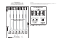
4.1.1 Program and Audition Analog Outputs
The program and audition outputs provide identical stereo performance, are active balanced, and factory calibrated,
with a 600 ohm load, to provide +4dBm when the front panel VU meters read “0” VU. This will provide in excess of
20dB of headroom. Adjustments for output levels, meter calibrates, and peak LED trip points are provided on the Ana-
log Output Board (with access to these controls via holes on the upper digital output board,) so that other output levels
maybe set.
The outputs will drive a 600 ohm load or higher. The outputs are connected via either a five position screw type barrier
strip or RJ-45 connectors that are mounted onto headers J30 (Program), and J29 (Audition), located on the Analog
Output Board.
Analog output levels for the Program, Audition and Tel buses can be pre-
trimmed or boosted in console software in .1 dB steps to a maximum of +4
dB out. Consult the “Output Level” page in the “Software” section of this
manual for more information.
When hand wiring the 5-pin connectors, is recommended that two conductor shielded cable, or two pair shielded cable
be used in wiring all balanced audio inputs to the console. To minimize RF interference and ground loops, the shields
should be tied to ground only at one end of the cable. See manual section 1.4.6 “Grounding and Shielding” for more
detailed information.
If an unbalanced console output is required, single conductor shielded cable or two conductor shielded cable with a
foil shield around each conductor should be used. The audio should be taken from the + Output terminal, while the
shield should be connected to Ground. In this case, the shield is connected at both ends of the cable. There should
be no connections to the - Output. In this configuration, the console output will provide -2dBm into a 600 ohm load
when the front panel VU meters read “0” VU.