
Specifications

Radio Systems Millenium-D Digital Console Page 3
3.2.1 Input Wiring.................................................................................................................. 19
3.3 Analog Daughter Cards .............................................................................................. 19
3.3.1 Unbalanced Analog Audio .......................................................................................... 19
3.3.2 Analog Mono Inputs - for Mic and Line Level ............................................................. 19
3.3.3 Input Sensitivity ............................................................................................................ 19
3.3.4 Phantom Power ............................................................................................................ 20
3.4 Digital Daughter Cards ................................................................................................ 20
3.4.1 Unbalanced Digital Audio............................................................................................ 20
3.5 “Patch-Point” Connections ........................................................................................... 20
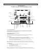
Illustration C-1 Analog input plug-In Board p/n 15303 ........................................................................ 21
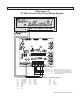
Illustration C-2 Digital Input Plug-In Board 15304 ............................................................................... 22
Illustration C-3 6 Input Mother BoardRJ-45 Connector Version .......................................................... 23
Illustration C-4 6 Input Mother Board5 Pin Connector Version ........................................................... 24
Output Boards .............................................................................................................. 25
4.0 Overview ...................................................................................................................... 25
4.1 Analog Output Board ................................................................................................... 25
4.1.1 Program and Audition Analog Outputs ........................................................................ 25
4.1.2 “TEL” Output ............................................................................................................... 26
4.1.3 External Monitor and Headphone Inputs ................................................................... 26
4.1.4 Headphone Outputs .................................................................................................... 26
4.1.5 Monitor Sends .............................................................................................................. 26
4.2 Digital Output Board .................................................................................................... 27
4.2.1 Digital Program Outputs .............................................................................................. 27
4.2.2 Digital Utility Outputs .................................................................................................. 27
4.2.3 RS-232 Connectivity .................................................................................................... 27
4.2.4 Clock Rate (Digital Sync.) ............................................................................................ 28
4.2.5 Eight Position Switcher ................................................................................................ 28
4.3 Control Wiring .............................................................................................................. 28
4.3.1 Mute and Timer Reset Bus Connections .................................................................... 28
4.4 Talk Back Connections ................................................................................................ 28
4.5 Intercom Kit ................................................................................................................. 29
4.6 Internal Adjustments and Level Calibration ................................................................. 29
4.6.1 Program Bus Output Level Adjust ............................................................................... 29
4.6.2 VU Meter “0” Calibration .............................................................................................. 30
4.6.3 Peak LED Trip Point Calibration ................................................................................... 30
4.6.4 External Monitor Input Level ........................................................................................ 30
4.6.5 Cue Bus External Input Level ...................................................................................... 30
Illustration D-1 Analog Output and Meter Board 5-Pin ....................................................................... 31
Illustration D-2 Analog Output and Meter Board RJ-45 ...................................................................... 32
Illustration D-3 Digital Output and Processor Board RJ-45 ................................................................ 33
Illustration D-4 Digital Output and Processor Board 5-Pin ................................................................. 34
Illustration D-5 Auxiliary Control Relay Wiring ...................................................................................... 35
Illustration D-6 Talkback Wiring ............................................................................................................ 36
Illustration E-1 Enhanced Remote Interface Card ............................................................................... 37
Illustration E-2 Four Source Router Card ............................................................................................. 38
Illustration E-3 DA Mixer Card ............................................................................................................. 39
Illustration E-4 DA Mixer Card Programming Examples ...................................................................... 40
Illustration E-5 Intercom Wiring Card................................................................................................... 41
Illustration E-6 Intercom Card Table-Top Speaker & Console Interconnection ................................... 42
5.1 Description – Overview ................................................................................................ 43
5.2 Operation ..................................................................................................................... 43
5.3 Installation and Wiring ................................................................................................. 43
5.3.1 Control Wiring .............................................................................................................. 43
5.3.2 Intercom card audio wiring .......................................................................................... 43
5.3.2.1 Console internal wiring ................................................................................................ 43
5.3.2.2 Table-top speaker wiring ............................................................................................. 43