
Specifications

Radio Systems Millenium-A Console Page 4
Illus. E-3 Four Source Router Card ...................................................... 36
Illus. E-4 DA-Mixer Card ....................................................................... 37
Illus. E-5 DA-Mixer Programming Examples ........................................ 38
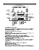
Illus. E-6 Intercom Card Wiring ............................................................. 39
Illus. E-7 Intercom Card Speaker & Console Interconnection .............. 40
5.2 Intercom Card Overview ........................................................ 41
5.2.1 Operation ....................................................................... 41
5.2.2 Installation and Wiring ................................................... 41
5.2.2.1 Control Wiring ................................................................ 41
5.2.2.2 Intercom card audio wiring............................................. 41
5.2.2.3 Console internal wiring .................................................. 41
5.2.2.4 Table-top speaker wiring ................................................ 41
5.2.2.5 Console interconnection ................................................ 41
5.2.3 Calibration ...................................................................... 42
Maintenance and Troubleshooting ...............................................43
6.1 Overview ................................................................................ 43
6.2 Power Supply ........................................................................ 43
6.3 Six Channel Audio Board ...................................................... 43
6.4 Six Channel Control Board ................................................... 44
6.5 Output Board ........................................................................ 44
6.6 Changing VCAs ..................................................................... 44
6.6.1 Distortion Null Adjustment.............................................. 44
Theory of Operation ........................................................................46
7.1 Power Supply Circuit Description ......................................... 46
7.1.1 Grounding ..................................................................... 46
7.1.2 Positive and Negative 7.5 volts ..................................... 46
7.2 Six Channel Control Board .................................................... 46
7.2.1 Brief Description ........................................................... 46
7.2.2 Detailed Description ...................................................... 46
7.3 Six Channel Audio Board Circuit Description ........................ 47
7.3.1 Brief Description ............................................................ 47
7.3.2 Detailed Description ...................................................... 47
7.4 Monitor Control Board ........................................................... 48
7.4.1 Brief Description ........................................................... 48
7.4.2 Detailed Description....................................................... 48
7.5 Output Board Circuit Description ........................................... 49
7.5.1 Brief Description ........................................................... 49
7.5.2 Detailed Description ...................................................... 49
7.6 RFI Suppression .................................................................... 50
7.7 Using Active Balanced Circuitry ............................................. 51
Schematics, Drawing and Parts Lists
Illustration Six Channel Control Board Schematic ................................ D-1
Illustration Six Channel Control Board Parts Layout Top ...................... D-2
Illustration Six Channel Control Board Parts Layout Bottom ................. D-3
List Six Channel Control Board Parts List ............................... D-4/5