
Specifications


Radio Systems Millenium-A Console Page 50
connected to the input of U20. Each external input has an associated trimmer for level adjustment. The voltage at U20
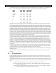
pins 6, 9, 10, 11 are generated on the Monitor Control Board. The truth table for input selection is as follows:
Input Pin 6 Pin 9 Pin 10 Pin 11
None High Low Low Low
Program Low Low Low Low
Audition Low Low Low High
Mono Low Low High Low
Cue Low Low High High
A Low High Low Low
B Low High Low High
C Low High High Low
D Low High High High
Integrated circuit U22B provides 32dB of gain to the selected signal. U22B drives the Unmuted Left Channel Monitor
Output, the input of VCA U26, and one of the inputs of U23, a 4053 type CMOS analog switch. VCA U26 is a dBx cur-
rent in, current out device, capable of over 100dB of level control. U24B is a current to voltage converter which drives
the Left Channel Monitor Output. Trimmer VR26 provides distortion null adjustment for the VCA. There are two voltages
available to control the gain of the VCA. The rst is generated by the front panel monitor level control, and the second is
generated by trimmer VR27 which is the monitor dim control. Whenever the Mute 1 Control Bus is high, U23 pin 9 will
also be high, and the wiper of VR27 will be connected to the positive input of U33A. Similarly, when the Mute 1 Control
Bus is low, U23 pin 9 will also be low and the wiper of the front panel monitor level control will be connected to the posi-
tive input of U33A. U33A buffers the selected control voltage and provides a negative offset so that the VCA will operate
at unity gain at normal level control settings, and will provide 15dB of gain at when the level controls are set at maximum.
When Mute 2 Control Bus is high, U23 pins 10 and 11 are also high and the selected monitor signal is disconnected from
the input of U24D which drives the Left Channel Muted Monitor Output.
The operation of the headphone amplier is similar to the monitor amplier. The inputs of U21 (the headphone input
select CMOS analog switch) are paralleled with U20. Selection of the input signal is identical to that of the monitor
amplier circuit with the exception of U27. The control voltages from the Monitor Control Board appear at U27 pins
1, 3, 5, and 7, while the control voltages from the Headphone Control Board appear at U27 pins 2, 4, 6, and 15. If no
headphone input switches are depressed, U19 will connect the control voltages from the Monitor Control Board to U21,
resulting in a headphone follows monitor conguration. Otherwise, the Headphone Control Board will select the desired
headphone input. Integrated circuit U22D drives a prefader headphone output, U31 is a dBx VCA, U30 is a power ampli-
er for driving headphones, and U33 buffers and offsets the VCA control voltage generated by the front panel headphone
level control.
The output of the Cue Bus current to voltage converter is connected to transistor Q6, which inhibits the cue audio from
reaching VCA U28, if the Mute 1 Control Bus is high. U29B is a power amplier for driving the cue speaker, and U29A
buffers and offsets the VCA control voltage generated by the front panel cue level control.
Talk back signals are gated by transistor Ql (which is controlled by the front panel talk back switch) prior to buffering and
amplication by UlB.
Transistors Q5, Q4, and Q3 provide open collector outputs for the Mute 1, Mute 2, and Timer Reset control buses re-
spectively.
7.6 RFI Suppression
Careful consideration has been given to Radio frequency Interference protection in the RS Series consoles. Internal
designs employed include RF bypass capacitors, ground plane circuit board technology, metal rap-around enclosures
and single point ground returns.
Still, because every RF environment is unique, some extremely intense RF locations, especially high AM elds, may still
experience some interference. These installations will require individual, on-site troubleshooting to eliminate the interfer-
ence.
1. Locate the source of the interference. RF may enter the console via input or output lines.
Turn off the channels via the channel on/off switch. If the RFI disappears, the source of the interference is
that channels input wiring.
If the RFI does not disappear, unplug the output connectors, one at a time, on the Output Board. When the
interference disappears, you have located the source of the AFI.