
Data Sheet

Radiocontrolli s.r.l refuses any responsibility for irregular uses of the devices and for
any possible lack or inaccuracy of the data and reserves the right to change in whole
or in part these information without notice.
Rev 3.0
Pag. 3 / 3
www.radiocontrolli.com
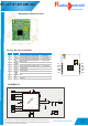
Recommended Hardware design
1) Hardware
All unused pins should be left floating; do not ground.
All GND pins must be well grounded.
Traces should not be routed underneath the module.
2) Power Supply
The transceiver module must be powered from a regulated voltage.
It is recommended to keep the power supply line for VCC as short and low impedence
as possible. Near the power pins it is recommended to insert a ceramic the decoupling
capacitor (100nF).
3) Ground Plane
It is recommended to have a copper ground plane under the module. The ground plane
should be unbroken.
4) Module Placement (PCB Antenna version)
The antenna on the PCB has an omnidirectional radiation pattern. To maximize antenna
efficiency, an adequate grounding plane must be provided under the module. Instead the
areas underneath and surrounding the antenna area must be free of copper.
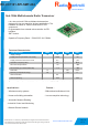
RC-CC1101-SPI-434
Radio
Wireless Modules
ontrolli
RC-CC1101-SPI-SMT-434