
User's Manual


MC-Series System Installation & Testing
Scheduled and Unscheduled Maintenance
102 RadioFrame Networks, Inc.
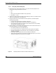
respective status LEDs. Reinsert the RBS. To do this, press up on one side rail locking
arm and press down on the other side rail locking arm, and then push the unit into the
rack (see the following illustration).
• BIC CRIC and AIC CRIC: The POWER and STATUS LEDs will light red and then green.
All other BIC and AIC card LEDs will light green.
7 Using the breaker on the PDU, turn up each RF Shelf and then verify that each RF Shelf is
operational before proceeding.
The POWER and ALARM LEDs on the front of the RF Shelf will light green.
8 Complete the procedures in sections 5.4, 5.5 and 5.6.
7.9.3 BIC/AIC– FRU Replacement Procedure
BEFORE REPLACING ANY CARD (board) in the BIC or AIC, power down RFN equipment in the
following order using circuit breakers on the PDU:
• BIC
• AIC
• RBS 1 (power down RBS 2 and RBS 3 if they are present)
• RF Shelves 1, 2 and 3
7.9.3.1 Replacing the CRIC (BIC or AIC)
1
Before replacing any card (board) in the BIC or AIC, power down RFN equipment in the
following order using circuit breakers on the PDU:
• BIC
• AIC
• RBS 1 (power down RBS 2 and RBS 3 if they are present)
• RF Shelves 1, 2 and 3
2 Always use a static grounding wrist strap before handling any board—do not attach the wrist
strap to any painted surface on the chassis unit.
3 Facing the BIC or AIC, remove the CRIC that is to be replaced, following these guidelines:
• Loosen the blue knurled knobs on both sides of the board.
• Pull firmly on the tabs located on the bottom of the CRIC.
• Gently slide the CRIC straight out and away from the chassis unit so as not to damage
any components contained on the board.
4 Remove the replacement CRIC from its antistatic packaging and insert it into the chassis unit
as shown in the following illustration, and follow these guidelines:
• Do not jam the board in any way while inserting it.