Radiolink Electronic Ltd www.radiolink.com WOLF QAV210 High Speed Aerial Videography Racing Drone Instruction Manual Radiolink Electronic Ltd www.radiolink.com * Please be kindly noted that this manual will be updated regularly and please visit Radiolink official website to download the latest version.
Radiolink Electronic Ltd www.radiolink.com Thanks for purchasing Radiolink WOLF QAV210. To fully enjoy the benefits of this product and ensure safety, please read the introduction carefully and set up the device as described below: If any problems found during the operation process, please kindly refer to the manual first. Then pilots could contact our distributors to find solution or follow our Facebook homepage https://www.facebook.com/Radiolink-1455452961436694/ to search related key words.
Radiolink Electronic Ltd www.radiolink.com bare wires may cause DANGER. Follow the instructions of props installation in case of dropping during flight. To ensure the best radio communication, please enjoy the flight at the space without interference such as high voltage cable, communication base station or lauching tower. WARNING This product is not a toy and is NOT suitable for children under the age of 18.
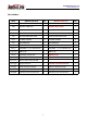
Radiolink Electronic Ltd www.radiolink.com Set includes: Name QAV210 Standard Qty QAV210 Advanced Qty Main Plate Carbon Fiber frame 1 Carbon Fiber frame 1 Radio Radiolink T8FB 8CH 1 Radiolink AT9S 10CH 1 Radiolink R8FM 1 Radiolink R12DSM 1 Radiolink Mini Pix 1 Radiolink Mini Pix 1 Radiolink M8N GPS TS100 1 Radiolink M8N GPS TS100 1 SZ-SPEED 2000KV 4 SZ-SPEED 2000KV 4 FLYCOLOR 30A 4 FLYCOLOR 30A 4 GEMFAN FLASH 5152S 8 GEMFANFLASH 5152S 8 FULLYMAX 11.
Radiolink Electronic Ltd www.radiolink.com Content Chapter 1 Introduction............................................................................................................................................ 6 1.1 Feature Highlights.......................................................................................................................................... 6 1.2 About WOLF QAV210...............................................................................................................
Radiolink Electronic Ltd www.radiolink.com Chapter 1 Introduction WOLF QAV210 is equipped with the flight controller Radiolink Mini Pix, fully powered by its functions of Pos-Hold, Auto Flight Mode, Waypoints Mode and RTL, perfectly works with Radiolink GPS with centimeter position accuracy to realize the function of pos-hold videography.
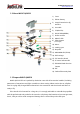
Radiolink Electronic Ltd www.radiolink.com 1.2 About WOLF QAV210 1) Cover 2) lithium battery 3) Image Transmission (IT) antenna 4) II module 5) F.C(Mini Pix) 6) RX (R12DSM/R8FM) 7) Power module 8) 9) MINI IT OSD Safety Button (Unlock flight ) 10) Motor 11) Landing gear 12) Propeller 13) MINI M8N GPS(TS100) 14) GPS carriage 15) I2C interface board 16) FC status indicate LED 17) FPV&DVR Dual-function Camera 18) ESC 19) Carbon fiber main plate 1.
Radiolink Electronic Ltd www.radiolink.com 1.4 Prepare Transmitter WOLF QAV210 has two versions, including stand-alone version and RTF version. ① pilots who purchase the stand-alone version, please follow the appropriate transmitter manual to install the receiver and bind the aircraft with the transmitter after receiving WOLF QAV210. ② RTF version includes the standard version with 8CH transmitter T8FB and the advanced version with 10/12CH transmitter AT9S.
Radiolink Electronic Ltd www.radiolink.com The 4 basic channels of all transmitters are always the same: CH1- Aileron/Roll; CH2Elevator/Pitching; CH3-Throttle; CH4-Rudder. These four basic channels are operated by the two sticks on the transmitter. Most transmitters have not only these 4 channels but also other auxiliary channels such as switches for changing fight modes, controlling PTZ and camera.
Radiolink Electronic Ltd www.radiolink.com More details about T8FB, please download the manual via the below link: https://mega.nz/#!4FMQRTYK!fxiu0KY-zJVrQkn1fSQY_hEDcCDQYgLH7c8GoSk_NiY More details about AT9S, please download the manual via the below link: https://mega.nz/#!AcNzVTiD!7ghFUypy5FldxARk6reAFGJ9w-Y4ALpv8qb5aCbcEmU All Radiolink products manuals available via the below link: http://radiolink.com.cn/doce/product-user-manual.html 2.1.2 Arm 2.1.2.
Radiolink Electronic Ltd www.radiolink.com Arm with Left Throttle: Toggle the left stick(Throttle) to the right bottom for 2s and a beep sound can be heard from the aircraft. The indicate color on flight controller will be flashing blue. Slightly push the throttle at the Stabilize Mode (If at Alt-hold Mode, the throttle better to be pushed over the central point), the motors and propellers start moving means the aircraft is successfully unlocked.
Radiolink Electronic Ltd www.radiolink.com Note: When the aircraft is to land, it is advised to change the flight Mode to STABILIZE MODE because it will be easier to disarm. Toggle the throttle to the vertical bottom for about 5s till the propellers stop moving then disarm the transmitter as the above steps. Otherwise the aircraft may be repeatedly up and down or rolled over as the result of trying to disarm in a rush.
Radiolink Electronic Ltd www.radiolink.com weather, pilots need to continuously correct the rolling and pitching angle to keep the aircraft at the same position. 2 Pilots use the rudder stick to control the turning velocity. When the rudder stick is loose, the aircraft will keep the direction. 3 Pilots use throttle to control the average rotation rate of the motors and need to continuously toggle the throttle to remain the aircraft at the certain height.
Radiolink Electronic Ltd www.radiolink.com throttle stick to the bottom outside corner, the aircraft will possibly rolling over. It’s better to wait for 10 more seconds till the aircraft detects landing and the motors stop completely to lock. 2.1.3.3 Pos-Hold Mode At Pos-Hold Mode, the aircraft will automatically keep current position, direction and altitude. That is, the aircraft will remain the same position if pilots don’t toggle sticks.
Radiolink Electronic Ltd www.radiolink.com RTL Mode works with GPS, which is indispensable to locate before changing to this Mode. The Mode commands the aircraft to return “HOME”where it takes off. Therefore, “HOME”should always be the place that the GPS locates where the aircraft actually takes off, without obstacles and far away from crowds. 2.1.
Radiolink Electronic Ltd www.radiolink.com Binding the transmitter to the receiver is essential. Otherwise, the aircraft cannot take off. Radiolink receivers R12DSM/R6DSM are compatible with transmitters AT9/AT9S/AT10/AT10II while R8FM is compatible with transmitter T8FB. Binding steps of all Radiolink transmitters and receivers are the same as follow: (1) Put the transmitter and the receiver together within 1 meter. (2) Power on the transmitter and the receiver.
Radiolink Electronic Ltd www.radiolink.com 2.2.3 Transmitter Parameters Setup The flight controller of WOLF QAV210 has been set with all necessary parameters before purchasing. For the stand-alone version, please calibrate the transmitter sticks, set the flight modes and Fail Safe. 2.2.3.1 Transmitter Calibration Before the transmitter sticks calibration in Mission Planner, please make sure the model type selected in transmitter is multi-rotors and the phase is REVERSED.
Radiolink Electronic Ltd www.radiolink.com Make sure binding between the transmitter and the receiver is complete before connecting Mini Pix with Mission Planner on computer via USB cable with the Baud Rate of 115200 . The connection between Mini Pix and Mission Planner can be also achieved by data transmission with the Baud Rate of 57600. Then power on the transmitter. Press PUSH to unlock the transmitter if no operation for a long time and it enters standby mode.
Radiolink Electronic Ltd www.radiolink.com Note: It’s strongly advised to install the propellers AFTER all parameters setup with the consideration of safety. And then click “OK” and move all RC sticks and switches to their ultimate positions so the green bars reach the limits/red lines.
Radiolink Electronic Ltd www.radiolink.com CH4: low position = yaw (anti clockwise), up position = yaw (clockwise). After each green bar reaches the limits/red lines, click the green button at bottom right to complete the transmitter calibration. 2.2.3.2 Flight Modes Setup Setup in transmitter Setup steps of Radiolink transmitter(T8FB/AT9S/AT10II) and flight controller with Mission Planner are as below.
Radiolink Electronic Ltd www.radiolink.com Stabilize M. Alt-Hold M. Pos-Hold M RTL M. Note: The following steps take AT9S as example, AT10II/AT10/AT9 can be set as the same way 1. When binding completed between transmitter and aircraft/receiver, click INITIAL SETUP =>MANDATORY HARDWARE => FLIGHT MODES 2.
Radiolink Electronic Ltd www.radiolink.com 3. Default channel is CH5 while setting the 3-way switch as SWC and the 2-way switch as SWA or SWD, pilots can personalize the setting basing on own flight habits Note: The PWM value ( RATE on the second column as below shown) can be modified with corresponding POSI (eg. UP-UP) while SWT is (ON). Toggle positions of SWC and SWA/SWD to select different POSI. Stabilize M. [ ATTITUDE ] CH: CH5 SW3: SwC - rate - - posi - SW2: SwD - swt - STABL.
Radiolink Electronic Ltd www.radiolink.com When setting the PWM value on transmitter, the corresponding PWM value on MP will change accordingly. Each flight mode has the PWM range and when the value is within, it means the current mode is set. Meanwhile, the selected mode on MP will turn dark green. That is , turning the dial on the transmitter to modify the RATE to make sure the corresponding PWM value on MP is within the range. Flight mode 2/3/4/5/5 can be set as the same way.
Radiolink Electronic Ltd www.radiolink.com There are different parameters setting such as throttle PWM, battery voltage to enable Mini Pix failsafe function. When the set parameter is reached, eg. If the throttle PWM value or the voltage is lower than the value set, then the failsafe is enabled and the aircraft will take corresponding action such as Return to launch(RTL), Continue to flight and Landing. To ensure the aircraft safety, RTL is normally set as the action following failsafe enabled.
Radiolink Electronic Ltd www.radiolink.com To activate the battery detector: • Monitor- 4 Battery and voltage • Sensor- 0: Other • APM version- 4: The Cube or Pixhawk To inactivate the battery detector: • Monitor- 0 disable When the detector is activated, the data could possibly fail to display. Please disconnect the flight controller from the computer and repower on the flight controller then open the above sheet to input the measured voltage. When 2.
Radiolink Electronic Ltd www.radiolink.com Mission Planner Setup After setting failsafe on transmitter, power it off and check the FAILSAFE menu on MP if the PWM value of CH3 is smaller than 975. If yes, than the FAILSAFE function is successfully set. Otherwise, the above steps need to be repeated. In the RADIO block on the right of the sheet, set ENALBLED always RTL and FS Pwm as 975. 2.2.
Radiolink Electronic Ltd www.radiolink.com (6) Hold the throttle to Minimum and disconnect the battery to exit ESC calibration mode. When all the above parameters set, propellers can be installed and arm the aircraft. For the arming steps, please refer to 2.1.2 RTF version Armed WOLF QAV210 racing drone is equipped with Radiolink MINI M8N GPS TS100 as factory default.
Radiolink Electronic Ltd www.radiolink.com Note: Never install the props when setting parameters of aircraft to ensure the safety. WOLF QAV210 is equipped with Radiolink MINI M8N GPS TS100 as factory setting. If the Pos-Hold Mode and RTL Mode needed, please go to an open space and wait till the satellites searched to enjoy the flight. Green indicator on GPS TS100 flashes means satellites searched. It’s advised to wait some time (about 1.5-2 mins) for searching satellites at the first flight.
Radiolink Electronic Ltd www.radiolink.com Different from visual flight, FPV is first person view with the help of a goggle or a screen. Theoretically, FPV flight is easier than visual flight because pilots can clearly judge the moment to turn or forward with goggle or screen. 3.2.1 FPV Goggle VR goggles for standard and advanced version of WOLF QAV210 are different. The standard version is equipped with the 3-inch FPV goggle from LONGSITE while the advanced one equipped with 4.
Radiolink Electronic Ltd www.radiolink.com ① Short press for menu displays, long press for more than 3s to power on/off. ② Short press for automatic search and channel with best signal will be selected. ③ Short press band+ with circular band changes from A - B- E - F - R.
Radiolink Electronic Ltd www.radiolink.com Top View Five-Way Button Antenna Connecto Channel Buttons DVR SD Card Slot Bottom View Power Switch USB Charge Port 2600 mAh 18650 Lithium Battery Brightness/ Contrast: Slide the 5-way button left and right or forward and back for contrast and brightness adjustment.
Radiolink Electronic Ltd www.radiolink.com FATSHARK 4.
Radiolink Electronic Ltd www.radiolink.com Instructions of CADDX Turtle 1080P FVP&DVR dual function camera ① Recording Button Short press the button to start or stop recording. The flashing red led indicates recording while always on indicates stop recording. ② SD Card Slot TF card is needed to insert into the slot when recording function is enabled. The maximum memory capacity of SD card supported by CADDX Turtle camera is 64G.