Digital 4-Channel Proportional RC System Instruction Manual RadioLink Electronics Co., Ltd Http://www.radiolink.com.cn CE FCC ROHS *.
MENU 1. 2. 3. 4. 5. Introduction and service………………………………………………………….2 Safety guides……………………………………………………………….....…. 2 Battery recharge notice……………………………………………………..….…3 Contents and specifications………………………………………………..…..….4 Receiver installation and binding…………………………………………………5 6 . Usage method of receiver intergrated with gyro and settings........................................6 7. Display when power switch turned on…………………………………….……...7 8. Language Select "LANGUAGE"………………....……………………………......9 9.
Introduction and Service Thank you for choosing RadioLink RC system, if you are the first time to use this type of products, please read this statement carefully and strictly in accordance with the requirements of operation. You could refer to the Manual if you meet any problems during the operation . Please well keep the manual after use because you might have to use it again next time. If you found any problems during the operation process, please refer to the manual.
The sequence to shut down is that turn off the receiver power first, and then shut down the transmitter. If the above operations are reverse, it might lead to uncontrolled situation and cause accidents The transmitter needs to be powered by 4 AA alkaline 5# batteries or Ni-MH batteries. Please check the voltage of batteries before using, as it might lead to uncontrolled situation and accidents when the voltage is lacked. So you must change the battery or recharge them in time.
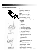
Contents and specifications Contents and Specifications: Contents: 1.Antenna 2.Binding key 3.Channel connection pin Specs: Size:51.5*24*15(mm) Channel number:4 channels Power standard:4.6-10V Frequency:2.4GHz Weight:5g Contents: 1. Antenna 2. LCD 3. Menu key 4. Turning wheel 5. Function key A throttle 6. Function key B Direction 7. Function key C the 3rd channel 8. The 3rd/4rd channel VR 9. The 3rd/4rd channel button 10. Recharge connection slot 11. Throttle trigger 12.Simulator port 13.Power switch 14.
Power standard:6VDC (1.5AA*4) RF power:less than 10dbm Power extending: JST port 2S~3S LiPo/LiFePo battery Modulation: FHSS Low voltage alert:Yes(lower than 4.6V) Data resolution:2048 Frequency:2.4GHz RF range: 300meters on ground Failsafe: in 1 second receiver fail getting signal from TX, the throttle will be 0, servos keep the last status. * RC3S standard equipment:A transmitter and a R4EH-H receiver. * RC4G standard equipment:A transmitter and a R4EH-G receiver.
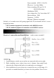
was not damaged, large circuit occurred. 4. Do not cut off or bind the receiver antenna, and try the best to keep it far away from metal and carbon graphite material. 5. Receiver is made up from precise electronic components, it need to be protected from vibration by packaged with sponge or other shock absorption materials. Code-matching method between transmitter and receiver: 1. 2. 3. 4. Load the battery into transmitter, power on it. Connect the power to the 2nd Channel pin of receiver.
3.Gyro usage method in forward and backward direction:When gyro in working state, pull the remote acceleraterto keep the car move forward for a distance, release the accelerator in the premise of not playing the direction key, turn around the car body, if the steering engine doesn't move , then gyro works in backward direction. You need to short press the code button for once(less than 1 second), the right light flashes once, then the gyro works in forward direction. 4.
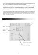
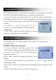
LCD Screen When you power on the transmitter, LCD screen shows battery voltage, R/C control system name, model name,steering trim,throttle trim ,the red light flashes two times Model Name The system can store the data for 10 models, model name will show on the LCD when you power on the transmitter. Please make sure the model name the screen displayed is the right what you want. If the model name you chose is not corresponding with your model, the pre-settings should be wrong.
Language Select "LANGUAGE" Both English and Chinese version menu are available for system,which is convenient for Chinese and English-speaking players to personalize function menus. 1. Access the function menu (By pressing “Exit” and “Enter” buttons simultaneously and holding them down for one second), the Language select function will be chosen. 2. Press “Enter” button to get into “LANGUAGE” function interface。 3.
End Point Adjuster "EPA" Use this when performing left and right steering angle adjustments, throttle high side/brake side operation amount adjustment, and channel 3 servo up side/down side operation amount adjustment during linkage. Correct the maximum steering angle and left and right steering angles when there is a difference in the turning radius due to the characteristics, etc. of the vehicle.
button to select the desired setting item , press “Enter” key the initial value of your selected setting item will blink, then you can press “Dec(-)” or “Inc(+)” button to adjust the value of your selected setting item. (Note: In the interface of adjusting the value, return to the initial value "120" by pressing “Dec(-)” and “Inc(+)” buttons simultaneously for about 1 second.) 3.
3. Press “Enter” button, the adjusted value of the rate stops blinking, now the value of the rate has been set. 4.Return to the initial screen by pressing“ Exit” button twice. Note: the Vertical cursor shown in the figure moves in step with steering wheel operation. Steering Speed "STSPD" Quick steering operation will cause momentary understeering, loss of speed, or spinning.This function is effective in such cases.
4. Press “Enter”button, the adjusted value of the selected setup item stops blinking, now the value of the selected setup item has been set. 5.Return to the initial screen by pressing “Exit” button twice. Throttle EXP "THEXP" This function makes the throttle high side and brake side direction servo operation quicker or milder. It has no effect on the servo maximum operation amount.For the high side, selection from among three kinds of curves (CRV/VTR/ EXP) is also possible.
“FWD-VTR” function. 2. Press “Dec(-)” or “Inc(+)” button to select RATE for forward side adjustment that you want, when the “MODE” value is “INT” the VTR will not work, only the “MODE” value set to “ACT” the VTR function is available. From the graph you will clearly see the changes you have made on TG.P and RATE. Adjustment method for EXP curve Setup items MODE: EXP turn on or turn off RATE: EXP rate Adjustment range MODEL: INT/ACT RATE: -100 ~ 0 ~ +100 1.
side when you want to make the rise milder. (Note: In the interface of adjusting the value, return to the initial value"0" by pressing “Dec(-)” and “Inc(+)” buttons simultaneously for about 1 second.) (2). Press “Enter” button, the adjusted BRK value stops blinking, now the BRKvalue has been set. 3. When ending setting, return to the initial screen by pressing “Exit” button twice.
function. 2. Press “Enter” button to get into THSPD function interface. 3.
3.
DLY:Delay amount CYC: Cycle speed TGP:Operation point DTY:Cycle duty ratio STM:Steering mixing -ABP : Amount of brake returnSets the rate at which the ser-vo returns versus trigger oper-ation for brake release. When set to 0%, the ABS function is not performed. When set to 50%, the servo returns 50% (1/2) of the trigger operation amount and when set to 100%, the servo returns to the neutral position. - DLY : DelaySets the delay from brake op-eration to ABS operation.
Select the setting item "ABP" by pressing “Dec(-)” or “Inc(+)” button,then press “Enter” key and the initial value of “ABP” will blink. Use “Dec(-)” or “Inc(+)” button to adjust the return amount. (Note: In the interface of adjusting the value, return to the initial value "50" by pressing “Dec(-)” and “Inc(+)” buttons simultaneously for about 1 second.) Press “Enter” button, the adjusted value stops blinking, now the value has been set.
3. (Pulse speed adjustment) Select setting item "CYC" by pressing “Dec(-)” or “Inc(+)” button, then press “Enter” key and the initial value of “CYC” will blink. Use “Dec(-)” or “Inc(+)” button to adjust the pulse speed (cycle). (Note: In the interface of adjusting the value, return to the initial value "5"by pressing “Dec(-)” and “Inc(+)” buttons simultaneously for about 1 second.) Press “Enter” button, the adjusted value stops blinking, now the value has been set.
(Note: In the interface of adjusting the value, return to the initialvalue"0"by pressing “Dec(-)” and “Inc(+)” buttons simultaneously for about 1 second.) Press “Enter” button, the adjusted value stops blinking, now the value has been set. "-3":Brake application time becomes shortest. (Brakes lock with difculty) "+3":Brake application time becomes longest (Brakes lock easily) (Remark) For low grip, set at the - side and for high grip, set at the + side. Duty ratio (DTY) -3 ~ 0 ~ +3 Initial value; 0 6.
7. When ending setting, return to the initial screen by pressing “Exit” button twice. Throttle Acceleration "ACCEL" Function which adjusts the movement characteristic from the throttle neutral position The servo will jump to the input position at its maximum possible speed. Unlike exponential, which adjusts the whole throttle movement into a curve, throttle acceleration simply "jumps" away from neutral and then leaves the remaining response linear.
Initial value: 0 2. (Brake side acceleration amount adjustment) Press “Dec(-)” or “Inc(+)” button to select “BRAK”, press“Enter”key to confirm and the initial value of “BRAK” will blink,then use“Dec(-)”or“Inc(+)”button adjust the acceleration amount. (Note: In the interface of adjusting the value, return to the initial value"0" by pressing “Dec(-)” and “Inc(+)” buttons simultaneously for about 1 second.) Press “Enter” button, the adjusted value stops blinking,now the value has been set.
1.Enter the function menu and use “Dec(-)” or “Inc(+) ” button to access IDLUP function. 2.Press “Enter” button to get into IDLUP function interface. 3.Press “Enter” key, and the initial value of RATE will blink. Use “ Dec(-)” or “Inc(+)” button to adjust the value. (Note: In the interface of adjusting the value,return to the initial value "0%"by pressing “Dec(-)” and “Inc(+)” buttons simultaneously for about 1 second.) Press “Enter”button,the adjusted value stops blinking,now the value has been set. 4.
3. Use “Dec(-)” or “Inc(+)” button to select ST channel, press “Enter” key,and the initial value of ST will blink. Use “Dec(-)” or “Inc(+)” button to adjust the center. (Note: In the interface of adjusting the value, return to the initial value"0"bypressing “Dec(-)” and “Inc(+)” buttons simultaneously for about 1 second.) 4.Press “Enter” key, the adjusted value stops blinking, now the center of ST has been adjusted. 5. TH channel and CH3 channel can be set similarly. 6.
Steering Dual Rate/Throttle Dual Rate "D/R" Dual rate The steering left and right servo travels are adjusted simultaneously.When you want to increase the servo travel, adjust the + side.When you want to decrease the servo travel, adjust the – side. Setup Item Steering D/R RATE Throttle D/R RATE Steering D/R rate (RATE) 0~100% Initial value: 100 Throttle D/R rate (Throttle D/R RATE) 0~100% Initial value: 100 1.Enter the function menu and use “Dec(-)” or “Inc(+)” button to access D/R function. 2.
ATL Function "ATL" Brake side adjustment This function decreases the set value when the braking effect is strongand increases the set value when the braking effect is weak. Setup Item RATE:Brake amount Brake amount (RATE) 0~100% Initial value: 100% 1.Enter the function menu and use “Dec(-)” or “Inc(+)” button to access ATL function. 2.Press “Enter” button to get into ATL function interface. 3.Press “Enter” key, and the initial value of RATE will blink. Use “Dec(-)” or “Inc(+)” button to adjust the value.
MXMD:Mix mode Enter the function menu and use “ Dec(-)” or “Inc(+)” button to access PMIX function, then press “Enter” button to get into PMIX function interface. 1.(Master channel) Channel selection (MST) ST, TH, CH3 Initial value: ST Select setup item"MST" by pressing “Dec(-)” or “Inc(+)” button, press“Enter” button, the initial master channel will blink.
“Dec(-)” and “Inc(+)” buttons simultaneously for about 1 second.) Press “Enter” key, the adjusted value stops blinking,the selected mixing amount has been adjusted. 4.(Right, brake or down side mixing amount adjustment) Mixing amount -100~0~+100 Select the setting item "RGHT", "BRAK", or "DOWN"(These setup items are different depend on the master channel.ST:"RGHT "; TH:"BRAK"; CH3:"DOWN ") by pressing “Dec(-)” or “Inc(+)” button.
Channel 3 and Channel 4 Position "AUX" Thechannel 3 and channel 4 servo position can be set from the transmitter.When CH3is assignedto the 3rd channel key,this setting is linked to the key.When CH3 and CH4 is not assigned to the 3rd channel key, it can be set with this screen. You can also set the CH3 and CH4 as VR at the same time, or SW. Channel 3 position (POSI) -100~+100 Channel 4 position (POSI) -100~+100 Initial value: 0 1.
3.After accomplish ment of naming,all characters of current name will stop blinking, the new namewill be stored automatically. 4.When ending setting,return to the initial screenby pressing“Exit” button twice.(the new setting model name will appear on the initial screen) Low battery voltage alarm The transmitter’s low voltage alarm adjustable, it depands on what kind of battery, the 4.6V is for 1s Lithium battery.Lower volt may cause the battery over discharge and damage the battery.
Be sure to reset Press “Enter” key, the symbol “YES” will stop blinking, and return to the initial screen. Now the model data is reset to the initial setting that is the default value set at the factory. Not to reset Press “Dec(-)” or “Inc(+)” button, the symbol “YES” will stop blinking and the symbol “NO” will blink, press “Enter” key, the symbol “NO” will stop blinking, return to the initial screen by pressing “Exit” button twice. Or you can press “Exit” button twice to quit resetting directly.