
Instructions / Assembly


5
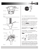
Loosen the set screws (2) in the support rod cou-
pler located on the top center of the motor hous-
ing (see figure 4) until the inside channel is clear.
Remove and save the safety screw from the cou-
pler.
Place coupler cover over the support rod cover.
Place rubber canopy ring over the coupler cover.
Place the ceiling canopy face down (small end)
over the support rod coupler on the motor hous-
ing.
Slide canopy onto support rod.
Feed the electrical wires from the fan housing
through the support rod.
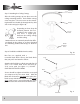
Thread the support rod into the support rod cou-
pler until the safety screw can be inserted
through the hole in both the rod and coupler.
Insert the safety screw through the hole in the
support rod coupler and support rod then tighten
firmly.
Insert the set screw in the coupler and tighten
firmly.
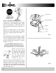
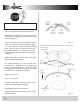
Step 3 Attach the support assembly
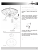
Ceiling Canopy
Half Ball Hanger
Support Rod
Support Rod
Set Screws
Support Rod
Coupler
Coupler Cover
Fig. 4
Safety Screw
Fig. 3
Motor
Motor
Housing
Cover
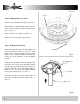
Insert the motor housing onto motor
Place motor housing cover onto motor, line up
the 3 keyway holes rotate plate; locking it into
place.
Insert single screw and tighten (see figure 3).
Tighten other 3 keyway screws.
Step 2 Attach Motor Housing to Motor
Rubber
Canopy Ring