
Installation guide


D6600/D6100 | Operation and Installation Guide | 4.0 D6600 Specific Cards
.
Bosch Security Systems | 4/05 | 4998122704F 9
3.2 D6100
3.2.1 Front Panel
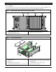
Figure 4: D6100 Communications Receiver/
Gateway (Front View)
1 – Liquid crystal display (LCD) - Displays up to 80
characters of information (two lines of up to 40
characters each)
2 – 23-button keypad
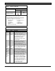
Table 2 and Table 3 on page 6 define the D6600/D6100
POWER and SYSTEM TROUBLE LEDs.
3.2.2 Line Cards and Modules
The D6100 Receiver/Gateway does not use the same
line cards and modules as the D6600. These functions
are built in.
3.2.3 Back Plate
Figure 5: D6100 Communications Receiver/
Gateway (Rear View)
1 2
7 6 5 4 3 2
1
1 – Telephone line
connections
2 – Input/output ports
3 – COM4 RS-232 port
4 – COM3 auxiliary
RS-232 port
5 – Parallel port
connection
6 – Ethernet port
(not available)
7 – Power connection
terminal block
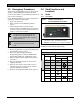
4.0 D6600 Specific Cards
4.1 D6640/D6641 Line Cards and D6645
Line Terminator Card
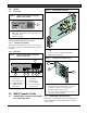
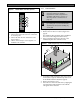
Figure 6: D6640/D6641 Line Card
1
2
3
1 – 48-pin connection to D6645 Line Termination
Card
2 – 40-pin connection to D6600 Back Plate
3 – LEDs (refer to Figure 8)
Figure 7: D6645 Line Terminator Card
1
3
2
1 – 48-pin connection to D6640/D6641 Line Card
2 – Alignment Guide - Stabilizes the connection
and acts as a guide for connecting the
terminator card to the line card.
3 – Telco Line Jacks - Standard telephone lines
connect to the RJ11C jacks.
4.1.1 D6640/D6641 LED Descriptions
The LED is active until the system acknowledges the
entire transmission and the telephone line is ready to
receive signals