
Specifications


Hardware installation
3
Install the CPM into an ATCA shelf
The CPM can be hot swapped, which means it can be installed while power is applied to the shelf. This
procedure assumes the power is already applied to the shelf.
1. Determine the node slot where the CPM will be installed. Do not use the slots reserved for the hub
modules (ATCA-2210 SCMs). For example, the hub slots are 7 and 8 on an ATCA-6000 and an
ATCA-6014 shelf, slots 1 and 2 on an ATCA-6006, and slots 8 and 9 on an ATCA-6016 shelf.
2. Remove the CPM from its ESD shielding bag.
3. Lift the ejector latches to the open position. Before inserting the CPM, inspect the EMC gasket to
make sure it is free of debris.
4. Holding the ejector latches in the open position, slide the CPM all the way into the shelf.
5. When the ejector latches reach the latch rail on the shelf, close both ejector latches but open the
bottom or right latch again right away (so only the top or left ejector latch remains closed). This
prevents the CPM from booting. In Set up the BIOS on page 4, you are instructed to close the other
ejector latch and tighten both retaining screws to secure the CPM in the shelf and start the bootup.
6. Make sure the front panel EMC gasket seals the surfaces it touches.
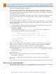
Front panel LED indicators
Connect a computer terminal to the serial port
This section explains how to connect a computer terminal in order to display and interact with the
operating system software.
1. Connect a serial cable to the serial port of the CPM. Cable details are provided in the ATCA-4500
Compute Processing Module Reference.
2. Connect the other end of the cable to the COM port of an external computer terminal, such as a
laptop. See Figure 1 on page 4 for a connection diagram.
3. Configure the terminal emulator on the external computer to match the default settings for the
CPM serial port: 115200 bps, no parity, 8 data bits, 1 stop bit, no flow control. For best display
results, the terminal should be set to 80 columns by 25 lines.
Note: If garbage characters are displayed, check that the same communication parameters are set
for both the serial port and the COM port.
Activity
Power
Out of service
Hot swap
LEDLabel ColorDefinition
LED 1
LED 2
LED 3
H/S
States
Off = Normal operation
Solid blue = Ready for hot swap
Amber = Application defined
Green = Power good
Red or amber = Out of service
Long blink = Searching for Shelf Manager
Short blink = Preparing for removal
Off = Normal operation
OOS
PWR
APP
H/S
Red / Amber
Green
Amber
Blue
Artisan Technology Group - Quality Instrumentation ... Guaranteed | (888) 88-SOURCE | www.artisantg.com