
Specifications


C
Connector Pinouts and Jumper Settings
144
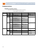
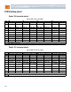
Zone 2 J20 connector pinout
31 EARLY_B –48 Volt Early B
–48 Volt input, Feed B precharge
First
32 ENABLE_A Enable A
Short pin for power sequencing, Feed A, tied to VRTN_A
on Backplane
Fourth
33 –48V_A –48 Volt A
–48 Volt input, Feed A, uses ENABLE_A to enable
converters
Second
34 –48V_B –48 Volt B
–48 Volt input, Feed B, uses ENABLE_B to enable
converters
Third
Gray indicates unused pins
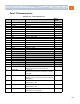
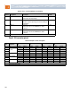
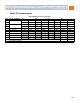
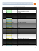
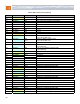
Table 43. Backplane connector J20 signals
Row
Interface
designation
AB CD EF GH
1 Clks CLK1A+ CLK1A– CLK1B+ CLK1B– CLK2A+ CLK2A– CLK2B+ CLK2B–
2 Update Channel
and Clks
Tx4(UP)+ Tx4(UP)– Rx4(UP)+ Rx4(UP)– CLK3A+ CLK3A– CLK3B+ CLK3B–
3
4 Tx0(UP)+ Tx0(UP)– Rx0(UP)+ Rx0(UP)–
5 Fabric Channel
15
6
7 Fabric Channel
14
8
9 Fabric Channel
13
10
Note: Each differential pair has an individual L-shaped ground contact (not shown).
Gray indicates unused pins
Table 42. Zone 1 contact assignments, P10 (continued)
Contact Designation Description
Mating
sequence