
Specifications
reset of the EPC-2 or setting bit RSTP in the .i.VSC; register terminates
driving of the MODID lines.
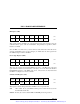
.i.TTL Trigger Drive Register; (.i.BTTD;)
TTD7 TTD6 TTD5 TTD4 TTD3 TTD2 TTD1 TTD0
815A
This read/write register drives the VXI TTL trigger lines; a 1 bit causes the
associated trigger line to be asserted. The actual change in state to the
trigger lines is synchronized to the 10 MHz .i.CLK10; to support the VXI trigger
.i.start/stop protocol;. Reading this register does not sample the triggers; it
simply returns what was previously stored in this register. Sampling the
trigger lines is performed with register .i.BTTS;.
A reset of the EPC-2 clears this register.
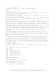
.i.ECL Trigger / Miscellaneous Register; (.i.BET;)
ES1 ES0 ED1 ED0 1 SBER 1 BSAM
815B
This read/write register contains the following bits:
ES Read-only bits that show the state of the ECL trigger lines on the
backplane (1 meaning asserted).
ED A 1 asserts the corresponding ECL trigger.
SBER ".i.Sticky BERR;." This bit is cleared whenever an VXI data-transfer bus
access by the EPC-2 is terminated by a .i.BERR;. By initially setting the bit
and then performing a series of data transfers, software can determine if a bus
error occurred. (Alternatively, software could examine the BERR bit in the
.i.BES; register after each access, or enable the BERR event to generate an
interrupt.)
BSAM This bit is 0 if a pipelined write is active from the EPC-2 onto the VXI
data-transfer bus. It allows software to wait for the completion of a write
(e.g., to determine when SBER can safely be examined after a series of writes).
.i.Unique Logical Address Register; (.i.BULA;)
815C
This register contains the EPC-2's .i.ULA;. Until a value is stored in this
register, the EPC-2's register base in the A16 space is FFC0, and it responds
only when its MODID is asserted. The ULA is changed by writing into this
register or into the .i.ID register; (.i.BID;).
.i.Module Status/Control Register; (.i.MSC;)
1 IST POSW BTOE WDTR FWDT 1 1
815D
This register contains the following miscellaneous status and control bits:
IST This bit specifies whether a response .i.status/ID; or an event status/ID
is used in an .i.interrupt acknowledge cycle;.
If IST is 0, the response format is used. In the 16-bit status/ID value
returned, the upper 8 bits are the value of the upper 8 bits of the .i.BRE;
.i.response register;, and the lower 8 bits are the EPC-2's .i.ULA;.
If IST is 1, the event format is used. The upper 8 bits of the status/ID
value are the value of the upper 8 bits of the .i.VMH; .i.message high
register;, and the lower 8 bits are the EPC-2's ULA. In this case software uses
the VMH register for the event code, meaning that .i.longword serial messages;
cannot be used at the same time.
POSW If set, writes to the .i.POS register; are enabled. (It is almost
certainly a mistake to set this bit without having interrupts disabled.)
BTOE Enables the slot-0 .i.bus timeout; timer. This is used by the BIOS.
Artisan Technology Group - Quality Instrumentation ... Guaranteed | (888) 88-SOURCE | www.artisantg.com