
Specifications

Theory of Operation
4 4
4-19
Refer to Appendix F, VMEbus Mapped Registers for additional information.
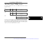
Passing VME Interrupts and Events to the CPU
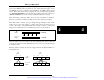
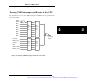
The diagram below shows how VME interrupts and VME events are generated and
passed to the CPU:
Figure 4-3. Passing VME Interrupts and Events to the CPU.
IRQ1
IRQ2
IRQ3
IRQ4
IRQ5
IRQ6
IRQ7
RRDY
WRDY
SYSFAIL
BERR (sticky)
ACFAIL
WDT
SIGNAL FIFO
RESET (sticky)
PC
architecture
IRQ10
VME
interrupt
state
register
VME
interrupt
enable
register
VME
event
state
register
VME
event
enable
register
Artisan Technology Group - Quality Instrumentation ... Guaranteed | (888) 88-SOURCE | www.artisantg.com