
Specifications


Chapter 3: Operation
17
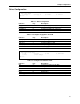
Table 3-8. ULA Setup
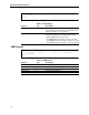
Table 3-9. Slave Memory Base
EXM Bus
Since there is only one EXM slot available, only one can be configured. When you select
EXM from the main menu, the following prompts display:
Enter the EXM ID = a hex value or ‘none’
Enter the EXM OB1 = a hex value
Enter the EXM OB2 = a hex value
Exit Menu
If you select ‘X’ at the main menu, the exit procedure starts. Changes take effect only after
a reboot.
Function Key Description
F8 (FE00) 0 Set ULA to FE00
F9 (FE40) 1 Set ULA to FE40
FA (FE80) 2 Set ULA to FE80
FB (FEC0) 3 Set ULA to FEC0
FC (FF00) 4 Set ULA to FF00
FD (FF40) 5 Set ULA to FF40
FE (FF80) 6 Set ULA to FF80
FF (FFC0) 7 Set ULA to FFC0
Function Key Description
Disabled 0 Disable Slave Memory Access
000000 (A24) 1 Set Slave Base Address to 0
400000 (A24) 2 Set Slave Base Address to 400000
800000 (A24) 3 Set Slave Base Address to 800000
C00000 (A24) 4 Set Slave Base Address to C00000
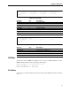
ULA Menu:
1) F8 (FE00) 2) F9 (FE40) 3) FA (FE80) 4) FB (FEC0)
5) FC (FF00) 6) FD (FF40) 7) FE (FF80) 8) FF (FFC0)
Choice:
Slave Base Memory Menu:
1) Disabled 2) 000000 3) 400000 4) 800000
5) C00000
Choice: