
Specifications


45
Connectors
This chapter specifies the details of the connectors and headers on the EPC-6A The
EXMbus connector is not defined here; its definition is available upon request.
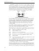
Front Panel LEDs
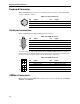
The EPC-6A has four discreet LEDs in the front panel’s top left corner. The front panel
also contains a seven-segment LED display. For detailed information about the seven-
segment LED display, see Front Panel Indicators on page 12.
Table A-1. LEDs
Speaker Connector
The speaker header on the EPC-6A circuit board is defined as:
Table A-2. Speaker Connector
LED Color Description
RUN Green Indicates that the EPC-6A’s memory is accessed. It first comes on at
power-up and should remain lit as long as the system is running.
If the LED is off, the most probable causes include both of these:
• A “hung” condition occurred in the operating system or application software.
• A VMEbus access is being attempted but the EPC-6A has not received a
bus grant. Typical reasons include: an error in setting the jumpers on the
VMEbus backplane, not being fully seated in the backplane, or a failure in
the SLOT 1 system controller module.
SYSFAIL Red Indicates a hardware reset or assertion of the VMEbus line. If a hardware
reset, the LED remains lit until the POST completes.
The LED is active only when the EPC-6A is jumpered as the SLOT 1 controller.
MASTER Indicates that the EPC-6A is performing a VMEbus access. The LED
remains lit from the time the 486DX2 processor initiates a read until the bus
operation completes or times out.
SLAVE Indicates another module performing a memory access into the EPC-6A’s
DRAM.
* The Master LED on and the Run LED off indicates that the EPC-6A stopped because either it can’t access
the bus, or because no module responded to the access and the access has not timed out.
Pin Signal Pin Signal
1 Reference voltage 2 Speaker tone
RESET
ABORT
RUN
SYSFAIL
MASTER
SLAVE
COM
Appendix A
A