
Specifications


EPC-6A Hardware Reference
48
Main Block #1 and #2 are reserved.
The EPC-6A employs Phoenix PicoBIOS version 4.05, implemented as a flash BIOS
using the 4 Mb (512 KB) Intel 28F004 SmartVoltage Boot Block. The Flash Boot Device
(FBD) contains a 16 KB boot block which holds the BIOS initializing and recovery code
Main block #3 contains an 8KB RadiSys manufacturing BIOS and the PicoFlash BIOS
extension.
The system BIOS code image resides in main block 4.
Parameter blocks 1 & 2 contain the System BIOS code.
The FBD is memory addressed and resides in the last 512KB of physical address space at
addresses 3F80000h through 3FFFFFFh. The System BIOS is shadowed and write-
protected at 0E0000h through 0FFFFFh (128KB) upon any system reset (warm boot,
shutdown, power-up or “reset button” reset).
The boot block, main blocks, and parameter blocks are protected against accidental writes.
Three register bits in the R400’s BIOS Control Register gate the WE# signal into the flash
parts, and the boot block is further protected by a jumper which must also be in place
before writes to the boot block can take place.
Forced recovery
A “force recovery” jumper is provided which is readable by the boot block and can force
the boot block to initiate a BIOS recovery sequence. This jumper is readable by the boot
block and can force the boot block to initiate a recovery sequence should the other
methods of initiating the sequence become inaccessible (for example, the System BIOS
becomes corrupted such that the system cannot boot to the OS).
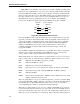
The following table describes the exact sizes and placement of the various code and data
objects present in the FBD:
The recovery process occurs because the boot block detects corrupt a BIOS or the force
recovery jumper is installed. System BIOS corruption is detected by calculating an 8-bit
checksum over the area occupied by System BIOS code.
The recovery is performed by using any Serial Communication Package (SCP) which
supports the XModem/CRC protocol. The SCP speed is determined automatically.
To determine the baud rate at which the SCP is running, the user repeatedly presses the
space bar. The autobaud mechanism should determine the baud rate that the SCP is
running at. If the baud rate is not determined before a predetermined timeout value, the
baud rate is defaulted to 9600 baud. The recovery module autobaud mechanism then
detects one of the following supported baud rates: 9600, 19200, 38400, 56800 or 115200.
The SCP executes on an external host computer and establishes a communication link with
the EPC-6A via the recovery serial port. The recovery mechanism supports the recovery of:
Table B-1. FBD object placement
Object Name FBD Offset Object Size Write Enable
Boot and recovery code 7C000h 16KB BB write-enable jumper
System BIOS 60000h 96KB In chipset
PicoFlash BIOS extension 4A000h 16KB In chipset