
Specifications
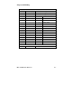
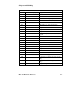


Chipset and I/O Map
EPC-100 Hardware Reference A-5
DMA Controller (cont’d)
I/O Addr Functional group Usage
0D4 Command register (R)
Single-bit DMA req mask(W)
0D6 Mode
0D8 Set byte pointer (R)
Clear byte pointer (W)
0DA Temporary register (R)
Master clear (W)
0DC Clear mode reg counter (R)
Clear all DMA req mask (W)
0DE All DMA request mask
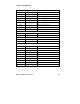
0E0 Phoenix BIOS Status Information
Coprocessor Interface
0F0 Coprocessor Clear coprocessor busy
0F1 Reset coprocessor
IDE Control
170 Secondary IDE Control Data Register
172 Sector Count
173 Sector Number
174 Cylinder LSB
175 Cylinder MSB
176 Drive/ Head
177 Status/ Command
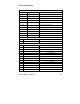
1F0 Primary IDE Control Data Register
1F2 Sector Count
1F3 Sector Number
1F4 Cylinder LSB
1F5 Cylinder MSB
1F6 Drive/ Head
1F7 Status/ Command