SCOPIA XT1000 Installation Guide Version 2.
© 2000-2010 RADVISION Ltd. All intellectual property rights in this publication are owned by RADVISION Ltd and are protected by United States copyright laws, other applicable copyright laws and international treaty provisions. RADVISION Ltd retains all rights not expressly granted. This publication is RADVISION confidential. No part of this publication may be reproduced in any form whatsoever or used to make any derivative work without prior written approval by RADVISION Ltd.
Table of Contents 1 Architecture Considerations About the SCOPIA XT1000 Series .......................................................................... 1 SCOPIA XT1000 Series as Endpoints ....................................................................... 1 SCOPIA XT1000 Series as Embedded MCUs............................................................... 2 Embedded MCUs and SCOPIA XT Desktop ................................................................ 4 Firewall/NAT Support ...................
Connecting the Video System ...................................................................... 17 Connecting the Main Camera ................................................................. 17 Connecting an Optional Camera ............................................................. 18 Using Optional Cameras with the XT1000 Remote Control Unit ........................ 20 Using a DVD or Blu-ray Player ................................................................
1 Architecture Considerations About the SCOPIA XT1000 Series The SCOPIA XT1000 Series incorporates the latest state-of-the-art video technology for room conferencing, including support for dual stream 1080p video, high quality data sharing, high quality full band audio and a high capacity embedded MCU. Among its key features, SCOPIA XT1000 delivers support for two full High Definition (HD) 1080p video streams as standard.
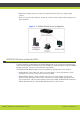
• High motion 720p60 capture is required. The Standard Camera does not support 60fps capture. • There are very low light conditions. In general, the Sony Camera captures better image in low light conditions. Figure 1-1 SCOPIA XT1000 Series as Endpoints SCOPIA XT1000 Series as Embedded MCUs The MCU capability is embedded in the SCOPIA XT1000 and can be activated by registering the Codec Unit serial number and product key in the XT1000 web registration page reserved to SCOPIA XT1000 purchasers.
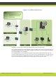
Figure 1-2 SCOPIA XT1009/XT1209 The figure illustrates how the embedded MCU performs media processing for connected terminals regardless of their location and handle multiple conferences simultaneously. We recommend enabling the High Bandwidth Option (12Mbps) when using the embedded MCU. If the High Bandwidth option is not enabled, the MCU will send out a lower resolution according to the standard 4Mbps total bandwidth. The embedded MCU can host Standard Definition (SD) and HD endpoints simultaneously.
Embedded MCUs and SCOPIA XT Desktop Built on the SCOPIA XT1000 HD room system with its high capacity embedded MCU, the SCOPIA XT Desktop solution combines HD room system capabilities, embedded multi-party conferencing, desktop conferencing and firewall traversal. The SCOPIA XT Desktop option is delivered on a CD for installation on a separate server.
ISDN Connectivity The SCOPIA XT1000 Series supports ISDN connectivity, allowing calls from endpoints to be routed to the relevant conference using the SCOPIA BRI (Basic Rate Interface) and PRI (Primary Rate Interface) gateways. RADVISION has implemented a special pairing mechanism between the gateway and the endpoint so that ISDN dialing is very simple. After pairing the systems, the participants place ISDN calls by dialing the remote party ISDN number.
RADVISION | Installation Guide for SCOPIA XT1000 Version 2.
2 Hardware Setup Safety Regulations For detailed safety information consult the SCOPIA XT1000 Safety Instructions leaflet enclosed in the delivery package. Prerequisites Room Setup Set up the conference room to enjoy the virtual meeting. SCOPIA XT1000 can receive the Infra-Red (IR) command of the Remote Control Unit via: 1. The Codec Unit IR receiver 2. The IR receiver of the XT1000 Standard Camera or the Sony Camera.
Figure 2-1 Suggested Room Setup Avoid white walls as they can introduce an effect-like backlight: a white wall increases the illumination behind the person. Avoid glass walls, as well as patterns and textures on the walls as they may cause disturbances to visual effects.We recommend to have plain walls of neutral color. Also, in order to avoid reverberations, we recommend to use heavy curtains of neutral color and carpets.
Setting Up the SCOPIA XT1000 Installing the Codec Unit Vertical Mounting The Codec Unit can operate in vertical (or horizontal) position. Procedure Step 1 Step 2 Remove the cover on the left side of the Codec Unit and insert it into its base. Using a flat-blade screwdriver fully turn the connecting screw on the base until it is completely secured. Figure 2-2 Codec Unit Vertical Mounting Step 3 With the codec in vertical position we recommend to use the support fairlead to avoid cable weight issues.
Note: If cascade cameras are used, RADVISION recommends connecting two cameras of the same type to the Codec Unit: two XT1000 Standard Cameras or two Sony Cameras. Note: RADVISION has certified the XT1000 Standard Camera and the Sony Camera for usage with SCOPIA XT1000. RADVISION has not certified other cameras and cannot guarantee their compatibility with the XT1000 Codec Unit. Integrators whishing to use other 3rd party cameras can do this at their own risk.
Step 6 Connect the LAN or GLAN input to the network . Note: From software version 2.0.7B only the GLAN input is enabled. You need to purchase a licence to use the LAN input. Step 7 Connect additional audio or video equipments to the available inputs/outputs (see Connecting the Audio System page 14 or Connecting the Video System page 17). Step 8 Step 9 Step 10 Connect the power supply of the Codec Unit. Step 11 Power the monitor on. Press the Power button at the back of the XT1000 Codec Unit.
Figure 2-5 LAN and GLAN Connection - Single Router • In case you need to connect the Codec Unit to a private network and a public network,and there are multiple routers in both networks, we recommend to connect the private network to the GLAN connection, and the public network to the LAN connection. Note: All the addresses belonging to IANA private internets (local networks) and listed below will be routed as private network addresses (i.e. 192.168.xxx.yyy): • 10.0.0.0 - 10.255.255.255 • 172.16.0.
Figure 2-6 LAN and GLAN Connection - Multiple Router • We do not recommend a connection where traffic is split between two I/O ports. This type of connection causes overcharge of memory usage and routing operations inside the Codec Unit. Figure 2-7 Not Recommended RADVISION | Installation Guide for SCOPIA XT1000 Version 2.
Connecting the Audio System Connecting the Microphone Array Pod The Microphone Pod performance varies with room characteristics, background noise levels, and loudness and position of speakers. When used in typical settings, the Microphone Pod can cover a radius of 2 meters (about 6.5 feet). For optimal results: • Place the Microphone Pod at the center of the table. • In a larger conference room, connect 2 Microphone Pods. Distribute them evenly on the table.
Figure 2-10 Connecting the Microphone Pods to the Codec Unit Note: Use 2 Microphone Pods maximum. Note: In the current version release, the XT1000 Codec Unit does not encode/decode stereo signals. Connecting an External Microphone System When the two-pod configuration does not suffice to cover the room, use an external microphone system. You need to acquire audio mixers from third-parties (e.g. Clear One).
RADVISION has tested and certified the use of bi-directional AU-D9 from CYP (UK) Ltd. The same audio converter is also called DCT-9 and is available in the RADVISION price list. For detailed information on the audio converter, see the DCT-9 Operation Manual on the company’s site. As an example of analog to digital conversion: you need to connect your PC to the Codec Unit so that the remote terminal hears the audio of the movie clip you’re just showing. Connect your PC to DCT-9 analog L/R input.
Figure 2-12 S/PDIF to Stereo Cabling Connecting the Video System Connecting the Standard Camera Use the XT1000 Remote Control Unit of the Codec Unit to control the Standard Camera. Note: The XT1000 Standard Camera is a high-end device with state-of-the art optics and full HD (1080p) support. Use the Sony Camera if you work with high-motion 720p60 capture. Note: CAUTION: Remove the camera stabilizing cartons before applying power to the camera. Connect the Standard Camera.
Figure 2-13 Connecting the Standard Camera Connecting an Optional Camera The optional camera kit contains a camera, remote control, and power supply. The kit does not contain cables since the optional camera location and distance from the Codec Unit varies significantly across installations. Use the Sony Camera when high motion 720p60 capture is required. This camera also supports up to 40x digital zoom.
Procedure Step 1 Connect the optional Standard Camera to the HDMI2 input of the Codec Unit. In this configuration, it is possible to send HDMI1 or HDNMI2 as main stream video. As a second stream video it is possible to send the signal present on the DVI input (usually a PC presentation). You can control both cameras (HDMI1 and HDMI2) by using the XT1000 Remote Control Unit.
Using Optional Cameras with the XT1000 Remote Control Unit To control the optional camera with the XT1000 Remote Control Unit, you will need to connect a VISCA Cross cable between the 2 cameras. VISCA Control is a standard protocol to control PTZ Cameras. Through the VISCA interface, the Codec Unit sends commands that change the camera capture resolution, PTZ properties and more.
Figure 2-16 Pinout Diagram • Step 2 The cable’s maximal length is 15m (50ft.). Connect the cable as explained in Connecting an Optional Camera page 18. Using a DVD or Blu-ray Player You may connect a DVD or Blu-ray player to the HDMI1 or HDMI2 inputs of the Codec Unit. When connecting a DVD player, be aware that according to the HDCP Licensee, you cannot use or transmit a digitally protected content. If the Codec Unit detects this type of content, the HDMI input is selected.
Figure 2-17 Connecting an Analog Camera As another example, you might need to connect an external recording device (e.g.: a DVD) to the Codec Unit. Connect the DVD to HD1 of the Codec Unit using the HDMI to Composite/S-Video Scaler. Connect the monitor to HD2. Figure 2-18 Connecting a DVD RADVISION | Installation Guide for SCOPIA XT1000 Version 2.
Connecting a Computer To share data during a call, connect a computer to the DVI-I IN socket of the Codec Unit. Procedure Step 1 (For computers and laptops with a DVI out connector) Connect the DVI cable to the DVI-I socket of the Codec Unit and connect the other end of the cable to the computer. Step 2 (For computers with VGA out only) Use the DVI to VGA adapter: 1. Connect the DVI-VGA adapter to the DVI-IN socket of the Codec Unit. 2. Connect a VGA cable to the adapter.
RADVISION | Installation Guide for SCOPIA XT1000 Version 2.
www.radvision.com About RADVISION RADVISION (NASDAQ: RVSN) is the industry’s leading provider of market-proven products and technologies for unified visual communications over IP and 3G networks.